Table of Contents
Advertisement
Quick Links
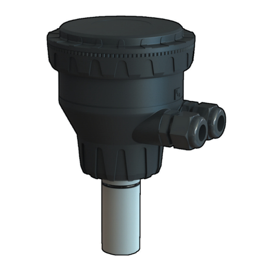
FLS F6.60
FLOW MAGMETER
Safety InStructIonS
General Statements
• Do not install and service the product without following the Instruction
Manual.
• This item is designed to be connected to other instruments which can be
hazardous if used improperly. Read and follow all associated instrument
manuals before using with it.
• Product installation and wiring connections should only be performed by
qualified staff.
• Do not modify product construction.
Installation and Commissioning Statements
• Remove power to the instrument before wiring input and output connections.
• Do not exceed maximum specifications using the instrument.
• To clean the unit, use only chemical compatible products.
1
Advertisement
Table of Contents

Related Manuals for FIP FLS F6.60


Summary of Contents for FIP FLS F6.60
- Page 1 FLS F6.60 FLOW MAGMETER Safety InStructIonS General Statements • Do not install and service the product without following the Instruction Manual. • This item is designed to be connected to other instruments which can be hazardous if used improperly. Read and follow all associated instrument manuals before using with it.
-
Page 2: Packing List
• USB pen drive with interface software • USB cable for instrument/PC interface DeScrIPtIon The new FLS F6.60 is a flow meter without moving mechanical parts which can be applied for the measurement of dirty liquids so long as they are conductive and homogeneous. -
Page 3: Technical Data
technIcal Data General • Pipe Size Range: DN15 to DN600 (0.5” to 24”) • Max Flow Rate Range: from 0.05 to 8 m/s (0.15 to 26.24 ft/s) • Full Scale: 8 m/s (26.24 ft/s) • Linearity: ± 1% of reading + 1,0 cm/s •... -
Page 4: Standards And Approvals
Enviromental • Storage Temperature: -30°C to +80°C (-22°F to 176°F) • Ambient Temperature: -20°C to +70°C (-4°F to 158°F) • Relative Humidity:0 to 95% (non-condensing) • Fluid conditions: - homogeneous liquids, pastes or slurries, also with solid content - min electrical conductivity: 20 μS - temperature: PVDF bottom version: -10 °C to +60 °C (14 °F to 140 °F) PEEK bottom version: -10 °C +150 °C (14 °F to 302 °F) -
Page 5: Installation
DImenSIonS Sensor body O-Ring (EPDM or FPM) F6.60 Magmeter Sensor body (316L SS or CuNi) Isolation Plate (PVDF or PEEK) Electrodes (316L SS or CuNi) Cable Gland ABS cap for installation into fittings Electronic box InStallatIon Pipe Location • The six most common installation configurations shown in fig. 1 help in selecting the best location in the pipeline for paddlewheel flow sensor as well for magmeter flow sensor. - Page 6 Fig.1 Fig.2 Fig.3 Fig.4...
-
Page 7: Mounting Position
Mounting position Measuring part of sensor (rotor for paddlewheel and pins for magmeter) should be positioned at 12% of ID where, basing on insertion theory, average velocity can be measured. The reading accuracy of insertion fl ow sensors can be affected by: •... -
Page 8: General Recommendation
WIrIng General recommendation Always ensure the power supply is switched off before working on the device. Make wiring connections according to wiring diagrams. • Terminals accept 26 to 12 AWG (0.08 to 2.5 mm2) • Strip around 10 mm (0.4”) of insulation from the wire tips and tin bare ends to avoid fraying. - Page 9 PoWer/looP WIrIng DIagram Stand-alone application, Connection to a PLC with built-in no current loop used power supply (3 wire connection) Power Supply PLC Terminals + VDC 12 - 24 VDC + LOOP Power Supply + VDC + LOOP Power Supply 12 - 24 VDC - LOOP - LOOP...
- Page 10 SolID-State relay WIrIng DIagram Connection to a PLC with NPN input Connection to a PLC with PNP input Internal PLC connection Internal PLC connection Power sup. Power sup. Power sup. Power sup. O.C. IN O.C. IN O.C. IN O.C. IN N.O.
- Page 11 oPen collector WIrIng DIagram Connection to FLS Instruments Frequency Output Direction Output - FREQ - FREQ FLS monitor FLS monitor terminals terminals + FREQ + FREQ - DIR - DIR FREQ IN + DIR FREQ IN + DIR - FREQ - FREQ FLS monitor FLS monitor...
- Page 12 earthIng The magmeter normally is uninfl uenced by low levels of electrical noise. In some applications it is necessary to connect the sensor to earth to eliminate electrical noise. The earthing can be done as following described: • connecting the Ground Wire (black wire from the sensor body) to an External Earthing passing through a cable gland.
-
Page 13: Manual Calibration
calIBratIon Manual Calibration Manual calibration can be done setting the micro switches on PCB in the proper combination in according with the pipe size (from d20-DN15 up to d>200-DN>180) where sensor will be installed. Positions are reported in the following table. Lock position is a No Functioning Combination while the USB combination is for accessing to the USB connection. - Page 14 calIBratIon By uSB The F6.60 flow magmeter can be connected to a PC and the operator can be connected to a PC and the operator can calibrate the instrument and set all parameters using dedicated software on USB pen drive (software can be dowloaded freely from FLS website) Procedure for setting - plug FLS Pen Drive into a USB port of PC...
-
Page 15: Output Mode
outPut moDe The F6.60 flow magmeter features 1 solid state relays and 1 analog output 4-20mA in addition to a Open Collector for frequency remoting (mainly for the interfacing of F6.60 with a FLS monitor) and a Open Collector for the flow direction remoting. - Page 16 f6.60 k-factor taBle (only for frequency outPut) K-Factor is the number of pulses which a sensor produces for one liter of measured fluid. Here below all K-Factors for water at room temperature are listed. K-Factor values can depend on the installation conditions. K-Factor has to divide the frequency generated by F6.60 in order to achieve the flow rate (l/s).
- Page 17 BSP female threaded PVc tee fittings for BS Solvent Welding PVc tee fittings for for BS Pn12 pipes BS Pn12 pipes (parallel threaded female ends) (female ends for solvent welding) Part no. k-factor Part no. k-factor TFFV20B 1/2" 462,04 TFLV20B 1/2"...
- Page 18 Installation on C-PVC pipes ISo metric cPVc tee fitings for ISo SDr 21 ISo clamp Saddles for ISo SDr 21 pipes pipes (female ends for solvent welding) Part no. k-factor Part no. k-factor SCIC063BVC 39,88 TFIC20B 462,04 SCIC075BVC 28,19 TFIC25B 272,89 SCIC090BVC 19,55...
- Page 19 nPt female threaded PP tee fittings for ISo clamp Saddles for ISo SDr 21 pipes aStm Sch.80 pipes Part no. k-factor (nPt threaded female ends) SCIC063BME 42,40 Part no. k-factor SCIC075BME 29,86 TFNM20B 0.50" 1/2" 510,01 SCIC090BME 20,71 TFNM25B 0.75" 3/4"...
- Page 20 Installation on PVDF pipes ISo metric PVDf tee fittings for ISo SDr 33 ISo clamp Saddles for ISo SDr 33 pipes pipes (female ends for socket welding) Part no. k-factor Part no. k-factor SCIC063BF 37,20 TFIF20B 510,01 SCIC075BF 26,06 TFIF25B 294,29 SCIC090BF 18,09...
- Page 21 Special Installation on DN 250 and DN 300 pipes PVc Wafer fittings PP Wafer fittings Part no. k-factor Part no. k-factor WFIC280B on request WVIC280B on request WFIC315B on request WVIC315B on request WFIC280D on request WVIC280D on request WFIC315D on request WVIC315D on request...
-
Page 22: Ordering Data
orDerIng Data Power main wetted flow rate Weight Part no. Version length enclosure supply materials range (gr.) 316L SS/ PVDF/ 0,05 – 8 m/s F6.60.09 Blind 12 - 24 VDC IP65 EPDM bi-directional 316L SS/ PVDF/ 0,05 – 8 m/s F6.60.10 Blind 12 - 24 VDC... -
Page 23: Spare Parts
SPare PartS Weight Part no. name Description (gr.) F6.KC1 Compact mounting kit Plastic adapter with compact cap and locking nut M9.SP4.1 PG 11 PG 11 complete cable gland (2 o-rings and cap) F3.SP3.1 O-Rings EPDM Sensor body O-Rings F3.SP3.2 O-Rings FPM Sensor body O-Rings F6.60. - Page 24 - formatura Iniezione Polimeri S.p.a. Loc. Pian di Parata 16015 Casella Genova - Italy Tel. +39 010 96211 Fax +39 010 9621209 www.flsnet.it...
Need help?
Do you have a question about the FLS F6.60 and is the answer not in the manual?
Questions and answers