Table of Contents
Advertisement
Quick Links
FLS M9.08
DUAL-PARAMETER
pH/ORP AND
FLOW MONITOR & TRANSMITTER
SAFETY INSTRUCTIONS
General Statements
• Do not install and service the product without following the Instruction
Manual.
• This item is designed to be connected to other instruments which can be
hazardous if used improperly. Read and follow all associated instrument
manuals before using with it.
• Product installation and wiring connections should only be performed by
qualified staff.
• Do not modify product construction.
Installation and Commissioning Statements
• Remove power to the instrument before wiring input and output connections.
• Do not exceed maximum specifications using the instrument.
• To clean the unit, use only chemical compatible products.
PACKING LIST
Please verify that the product is complete and without any damage.
The following items must be included:
• M9.08 Dual-Parameter pH/ORP and Flow Monitor & Transmitter
• Instruction Manual for M9.08 Dual-Parameter pH/ORP
and Flow Monitor & Transmitter
1
Advertisement
Table of Contents

Related Manuals for FIP FLS M9.08


Summary of Contents for FIP FLS M9.08
- Page 1 FLS M9.08 DUAL-PARAMETER pH/ORP AND FLOW MONITOR & TRANSMITTER SAFETY INSTRUCTIONS General Statements • Do not install and service the product without following the Instruction Manual. • This item is designed to be connected to other instruments which can be hazardous if used improperly.
-
Page 2: Technical Data
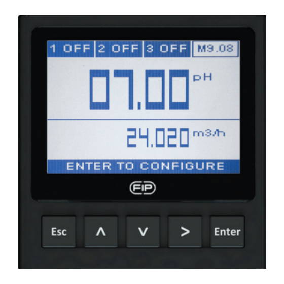
DESCRIPTION The new FLS M9.08 is a dual monitor which combines pH/ORP and flow measurements. A 4” wide full graphic display shows measured values clearly together with many other useful information. Moreover, due to a multicolor display plus a powerful backlight, measurement status can be determined easily from afar also. - Page 3 • Temperature input range: -50÷150°C (-58÷302°F) (with Pt100-Pt1000) • Temperature measurement resolution: 0,1°C/°F (Pt1000); 0,5°C/°F (Pt100) • Flow input range (frequency): 0÷1500Hz • Flow input accuracy (frequency): 0,5% Electrical • Supply Voltage: 12 to 24 VDC ± 10% regulated • Maximum current consumption: 300 mA •...
-
Page 4: Panel Mounting
DIMENSIONS PANEL MOUNTING WALL MOUNTING INSTALLATION Mechanical installation The M9.08 Dual-Parameter pH/ORP and Flow Monitor & Transmitter is available just in one packaging for panel or wall installation. The panel version is installed using the panel mounting kit (M9.SN1), while the wall mounting version is got fixing the panel mounting version on the wall mounting kit (M9.KW1). - Page 5 Panel installation Fix instrument on the panel rotating by hand the fixing snails (M9.SN1). Wall installation Use the panel mounting kit (M9.SN1) to fix the M9.08 on the dedicated frontal cutout of the wall mounting kit (M9.KWX). Tighten front screws of box and waterproof connectors of cables, internally mount caps on screw sites to get a IP65 watertight installation.
- Page 6 WIRING General recommendation Always ensure the power supply is switched off before working on the device. Make wiring connections according to wiring diagrams. • Terminals accept 26 to 12 AWG (0.08 to 2.5 mm • Strip around 10 mm (0.4”) of insulation from the wire tips and tin bare ends to avoid fraying.
-
Page 7: Probe Wiring Diagram
Refer to dedicated sensor manual for its wiring. In case a temperature sensor (Pt100-Pt1000) is not available, place a brigde connection between 28 - 29 and between 29 - 30. POWER/LOOP WIRING DIAGRAM Stand-alone application, Connection to a PLC with built-in no current loop used power supply Power Supply... - Page 8 Pt100 - Pt1000 no connection PT100/1000 USB PORT A USB port (type B) is available on the M9.08 PCB. The USB connection allows the updating of device software. To update the software you need: USB cable (M9.KUSB), the interface software "FLS Calibration System”...
-
Page 9: Operational Overview
The alarm is off during normal operation and goes ON according to Imax Relay setting. External Relay If Imax > 50 mA use external Relay N.C. N.O. Imax N.O. V= 12-24 VAC/VDC lmax = 50mA Imax = 50 mA RELAY WIRING DIAGRAM (FOR RELAY 1 & RELAY 2) The alarm is OFF during normal The alarm is ON during normal operation and goes ON according... - Page 10 VIEW LEVEL **** MENU DIRECTORY Settings pH/ORP - temperature Output Settings *** pH/ORP - flow Flow settings pH/ORP - temperature - flow item code - software release Calibration pH/ORP or temperature or flow - analog output 1 pH/ORP or temperature or flow - analog output 2 Flow Calibration pH/ORP direct access to calibration*...
- Page 11 MENU LEVEL Settings Probe Unit Manual Temperature Temperature Unit Flow Settings K Factor Volume Unit Flow Unit Calibration Temperature Probe Calibration pH/ORP Probe Calibration Flow Calibration Correction Factor Signal Intensity BLE Auto Calibration Outputs 1 SSR Output Test 2 SSR 4-20mA1 3 RELAY 4-20mA2...
-
Page 12: Output Mode
EDIT LEVEL PUSH BUTTON to modify an item to scroll right to return to Menu without saving to save new settings OUTPUT MODE The M9.08 Dual-Parameter pH/ORP and Flow Monitor & Transmitter features 2 solid state relays and 2 mechanical relays in addition to 2 analog output 4-20mA freely.Only the second mechanical relay can be set as a pH/ORP alarm (icon is 4ALR) related to the feedback of external device managing. - Page 13 Digital outputs can be set in the following way: pH/ORP ON-OFF MODE (icon reports O-F) ON-OFF MODE (icon reports O-F) LOW LEVEL HIGH LEVEL pH/ORP pH/ORP Hysteresis Setpoint Hysteresis Output relaxed Time Output relaxed Time Output energized Output energized PROPORTIONAL MODE (icon PROPORTIONAL MODE (icon reports PRP) LOW LEVEL reports PRP) HIGH LEVEL...
-
Page 14: Software Updating
MAX MODE (icon reports MAX) Setpoint Hysteresis Output relaxed Time Output energized FLOW MIN MODE (icon reports MIN) MAX MODE (icon reports MAX) Flow Flow Hysteresis Setpoint Hysteresis Setpoint Output relaxed Time Time Output relaxed Output energized Output energized WINDOW MODE (icon reports WDW) PULSE MODE (icon reports PLS) Flow Pulse duration... -
Page 15: Ordering Data
- Connect M9.08 to the laptop by the USB cable - Select the item (M9.08) which appears on the navigation area on the "FLS Calibration System" software - Confirm FW UPGRADE and select the Updated Software NOTE: At the end of the procedure restart the instruments in order to refresh M9.08 software (It takes 90 seconds to refresh the SW. - Page 16 FIP - Formatura Iniezione Polimeri S.p.A. Loc. Pian di Parata 16015 Casella Genova - Italy Tel. +39 010 96211 Fax +39 010 9621209 www.flsnet.it...
Need help?
Do you have a question about the FLS M9.08 and is the answer not in the manual?
Questions and answers