Table of Contents

Related Manuals for Network Technologies NTI UNIMUX UNIMUX-USBV-4


Summary of Contents for Network Technologies NTI UNIMUX UNIMUX-USBV-4
- Page 1 NETWORK TECHNOLOGIES INCORPORATED UNIMUX-USBV-4/2 (4/2-Port USB KVM Switch) INSTALLATION / USER GUIDE Tel:330-562-7070 1275 Danner Dr Aurora, OH 44202 Fax:330-562-1999 www.nti1.com UNIMUX Series MAN026 Rev Date 8/19/2003...
-
Page 2: Warranty Information
A return authorization number is required for all repairs/returns. COPYRIGHT Copyright © 2003 by Network Technologies Inc. All rights reserved. No part of this publication may be reproduced, stored in a retrieval system, or transmitted, in any form or by any means, electronic, mechanical, photocopying, recording, or otherwise,... -
Page 3: Table Of Contents
Available Options:... 1 MATERIALS ... 1 FEATURES AND FUNCTIONS... 2 INSTALLATION... 3 Power-Up Sequence... 5 USING THE NTI SWITCH... 5 Front Panel Control... 5 Keyboard Control... 5 MODES OF OPERATION ... 6 Basic Command Mode ... 6 Broadcast Mode... 7 Scan Mode... - Page 4 Figure 14- Information provided by the F3 command ... 19 Figure 15- Keyboard Layouts ... 21 Figure 16- Cascaded UNIMUX-USBV-4O USB KVM switches ... 22 Figure 17- Cascaded configuration with multi-user slaves ... 23 Figure 18- Cascaded switch cable connections... 24...
-
Page 5: Introduction
A USBVEXT-xx-MM cable for each USB CPU being connected to the switch must be used for monitor and device (keyboard and mouse) interface. Legend: xx is the length of the cable in feet MM indicates male-to-male connector Cables can be purchased from Network Technologies Inc by calling (800) 742-8324 (800-RGB-TECH) in the US and Canada or (330) 562-7070 (worldwide). -
Page 6: Features And Functions
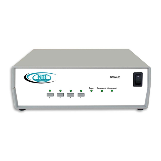
3. CPU Status LEDs- for visual indication of switch connection between the user and a specific CPU 4. CPU Select Switch- press to manually switch to a specific CPU or to change the switch operating mode 5. MONITOR- 15HD female connector- for connection of the user video monitor 6. -
Page 7: Installation
INSTALLATION INSTALLATION It is not necessary to turn OFF power to any of the CPUs that will be connected to the UNIMUX-USBV-4 USB KVM switch before connecting or disconnecting any cables. NOTE: If a CPU needs to identify a keyboard, it will be necessary to power ON the CPU after it is connected to the UNIMUX-USBV-4 USB KVM switch and only after the keyboard is connected and the UNIMUX-USBV-4 USB KVM switch is powered ON. -
Page 8: Figure 2- Connect A Cpu
Using the 15HD male video connector ends of the same USB-VEXT-xx-MM, connect the video port of the same USB CPU connected in step 5 to the female 15HD port labeled "VIDEO 1" on the UNIMUX-USBV-4 USB KVM switch . Be sure to tighten the two screws on the cable connector to the UNIMUX-USBV-4 USB KVM switch securely. -
Page 9: Power-Up Sequence
Power-Up Sequence The UNIMUX-USBV-4 USB KVM switch can be powered at any time. The CPUs can be powered at any time although if a CPU needs a keyboard and/or mouse at power-ON it should be powered after connecting to and powering-ON the UNIMUX-USBV-4 USB KVM switch. -
Page 10: Modes Of Operation
MODES OF OPERATION MODES OF OPERATION Basic Command Mode In order to control the UNIMUX-USBV-4 USB KVM switch with the keyboard connected, Command Mode must be enabled. To enter Command Mode from the keyboard: Press NOTE: IF THE OSD FEATURE HAS BEEN INSTALLED (ONLY AVAILABLE ON 4 PORT SWITCH), PROCEED DIRECTLY TO “OPTIONAL OSD CONTROL”... -
Page 11: Broadcast Mode
Scan Mode When in Scan Mode the switch scans to each port with a CPU powered-ON. (The SCAN LED on the front panel will illuminate and remain ON while in Scan Mode. ) The port with the CPU powered-ON remains active while in use until it becomes idle for the configured dwell time (default time-out period is 5 seconds) before switching to the next powered-ON CPU port. -
Page 12: Optional Osd Control
OSD is active. The current security status, idle time out, and scan dwell time are all saved and will be restored whenever power to the switch is cycled OFF, then ON. In the event the administrator password is lost or forgotten, to reset the administrator’s password call NTI and have the device serial number of the UNIMUX-USBV-4O USB KVM switch available. -
Page 13: User Login Mode
Once logged-in, follow the instructions on page 10 for setting up users and changing the password. Once the password is setup, if it is lost or forgotten the administrator will have to contact NTI for assistance on clearing the password and set it up again. The administrator can setup each of the users and the limitations of their use of the individual CPUs within the Administration Mode. -
Page 14: Administrator Password
The password can be up to 13 characters in length. NOTE: The default password for the administrator is ADMINISTRATOR. Function: Keystroke: Switch between Password and Verify Password fields Add character to password string or verify password string Delete previous character in edited string Save new password. -
Page 15: Edit User
b egue u] T J03.5(9880 TD0.Tc00.0002 Tw[ ( c8-Edit U)s us).1(esa anc).3(xess).3(xs ist ] T J0TT2 1 Tf9 0 0 9 57.6 7507.06Tm/0.0020 Edit User To enter the Edit User mode press <E> from the User Name List after selecting a user or an empty record. The Edit User mode (see Fig. -
Page 16: Alternate Command Hot Key
Key> combination. To disable it, the administrator should set <`> as the Alternate Command Hot Key. USER ACCESS FUNCTIONS USER ACCESS FUNCTIONS Command Mode In order to control the switch with the keyboard, Command Mode must be enabled. To enable Command Mode from the keyboard: Press Ctrl All the status lights on the keyboard will illuminate to indicate that Command Mode is enabled. -
Page 17: Figure 10- Additional Command Mode Options
Enter Change Settings Menu Enter Maintenance Mode Display Help Menu Select the first port on the switch Select the last port on the switch Select a specific port Enter Search Mode, add a character to search string and select the CPU’s name that matches best. -
Page 18: Scan Mode
To activate Edit Mode press <Ctrl> + <E> from the Command Mode menu. Edit Mode allows only the administrator to modify the names of the CPUs connected to the switch. Names of CPUs can be up to 12 characters in length. Characters typed can be upper or lower case. After changes have been made the administrator will be prompted by the menu to save the changes. -
Page 19: Change Settings
Edit Mode (Cont'd) Function: Keystroke: Move cursor to the previous port Move cursor to the next port When finished making changes in Edit Mode, press <Esc> and a prompt will appear to press either <Y> to save the changes or <N>... -
Page 20: Broadcast Mode Configuration
Broadcast Mode Configuration To enter the Broadcast Mode Configuration menu press <B> from the Change Settings menu (see Fig. 10). The Broadcast Mode Configuration menu (see Fig. 12) enables the user to select specific ports to be active in Broadcast Mode. Only the selected ports will receive keyboard messages in Broadcast Mode. -
Page 21: Mac Ports Configuration
Ports should be configured at installation time or whenever necessary. After setting, the configuration is stored in non-volatile memory and will be retrieved whenever the switch is power ON. When the port is connected to a Windows or SUN CPU, this configuration SHOULD BE DISABLED. By default, all ports are configured as non-MAC CPUs (Windows and SUN). -
Page 22: Search Mode
The Maintenance Mode functions allow placement of the window in a particular area of the monitor and the window will return there when the UNIMUX-USBV-4O USB KVM switch is reconnected to that particular CPU (provided the parameters are saved before exiting Maintenance Mode). -
Page 23: Help Mode
LEVEL 1 : PORT 5 LEVEL 2 : PORT 3 This means that the CPU connected through this port is actually connect through Port 5 of the master switch (Level 1), and through port 3 of the slave connected to port 4 (Level 2). -
Page 24: Keyboard Features
KEYBOARD FEATURES The keyboard configuration of each CPU is saved in the NTI UNIMUX-USBV-4 USB KVM switch. For example, if the CPU attached to Port 2 had CAPS LOCK and NUM LOCK selected the last time that CPU was accessed, then they will automatically be set when that CPU is accessed again. -
Page 25: International Sun Keyboards
(i.e. some Windows keyboards). To do this, manually set the UNIMUX-USBV-4 USB KVM switch to indicate the international keyboard identification number to the CPU by following the instruction on page 7 (for switches without OSD feature) or on page 16 (for switches with OSD feature). -
Page 26: Cascading
CPU ports may be connected to a UNIMUX-USBV-4O USB KVM switch. UNIMUX switches may be connected downstream (see Figs.16 and 17). The first switch in a cascaded system is referred to as the "master", while all downstream switches are referred to as "slaves". The only additional hardware required to cascade switches is a set of device and monitor cables for each “SLAVE UNIT”... -
Page 27: Limitations
USER and MONITOR ports that do not get connected to the master can be connected to by users. Users connected to a slave downstream from the master will control only the CPUs directly connected to that slave switch (i.e. users 5 and 6 in fig. 17 above can only control CPUs 25-40). -
Page 28: Operating Cascaded Switches
N T I N T I N T I Figure 18- Cascaded switch cable connections Operating Cascaded Switches Immediately after powering-ON the Master switch, the following splash screen will display on the monitor:... -
Page 29: Ddc Support (Optional)
When a keyboard key is pressed, the master switch will start the process of detecting the configuration. This could take several seconds, depending on how many switches are connected together. When configuration update is ready, the splash screen disappears and the system is ready to operate. -
Page 30: Troubleshooting
• reboot the CPU If the NTI UNIMUX-USBV-4 USB KVM switch still seems work improperly, help may be found in the Frequently Ask Questions (FAQ’s) section of our website at http://www.nti1.com or call us directly at ( 800) 742-8324 (800-RGB-TECH) or (330) 562-7070 and we will be happy to assist in any way we can.
Need help?
Do you have a question about the NTI UNIMUX UNIMUX-USBV-4 and is the answer not in the manual?
Questions and answers