Table of Contents

Subscribe to Our Youtube Channel
Related Manuals for Thies CLIMA Modbus


Summary of Contents for Thies CLIMA Modbus
- Page 1 >>First Class<< Instruction for Use 4.3151.xx.401 - Device with digital output (MODBUS RTU), RS 485 - Wind velocity signal acquisition Dok. No. 021887/12/20 T H E W O R L D O F W E A T H E R D A T A...
- Page 2 Safety Instructions • Before operating with or at the device/product, read through the operating instructions. This manual contains instructions which should be followed on mounting, start-up, and operation. A non-observance might cause: - failure of important functions - endangerment of persons by electrical or mechanical effect - damage to objects •...
-
Page 3: Table Of Contents
10.11 Command SN ......................20 10.12 Command SV ......................21 10.13 Command TR ......................21 10.14 Command TT ......................21 Command Interpreter MODBUS RTU ................. 22 11.1 Messwerte (Input Register) ..................23 11.2 Commands (Holding Register) ................. 24 Data Telegram ......................25 12.1 Telegram 3 ...................... -
Page 4: Available Models
Table overview Table 1: Commands ......................16 Table 2: MODBUS Frame ....................22 Table 3: MODBUS Exceptions .....................22 Table 4: MODBUS Input Register ..................23 1 Available Models Order - No. Winddirection Windvelocity Interface / Supply Heating South Measuring range Input [Hz] Data output bore* 4.3151.00.401... -
Page 5: Mode Of Operation
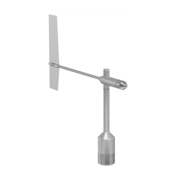
3 Mode of Operation Wind direction The dynamic characteristics of the wind vane is achieved by the aluminum lightweight con- struction. The co-action of wind vane and balance weight results in a high damping ratio with small delay distance as excellent characteristic of the complete vane. The axis of the wind vane is running in ball bearings and carries a diametrically magnetized magnet at the inner end. -
Page 6: Recommendation Site Selection / Standard Installation
4 Recommendation Site Selection / Standard Installation In general wind measurement instruments should be able to detect the wind conditions of a large area. In order to obtain comparable values when determining the surface wind, meas- urements should be taken at a height of 10 meters over an even area with no obstacles. An area with no obstacles means that the distance between the wind direction transmitter and an obstacle should be at least 10 times the height of the obstacle (s. -
Page 7: Wind Vane Mounting
5.1 Wind Vane Mounting Before the wind direction transmitter can be installed at its selected site, the wind vane must be mounted on the housing. Tool: Not required. Process 1. Remove wind transmitter shaft and wind vane from the packing. ... -
Page 8: Mechanical Mounting And Alignment
5.2 Mechanical Mounting and Alignment Remark: The wiring must be prepared so far, that plug and cable have been pushed through instru- ment carrier, mast, traverse etc., and can be connected to the wind direction transmitter at the moment of the “Mechanical Mounting”, described in the following (please refer to chapter 5.3.). - Page 9 Tools: Hexagon socket wrench size 3 (Allen key). Procedure: 1. Push cable/ plug connector of the wind direction transmitter through the borehole of the mast, tube, arm etc. 2. Put wind direction transmitter on mast, tube, arm etc. 3. For the precise determination of the wind direction the wind direc- tion transmitter must be aligned northwards (geographical north).
-
Page 10: Electrical Mounting
5.3 Electrical Mounting 5.3.1 Cable Solder a shielded cable with diameter 7 … 8mm and a core cross-section of 0.5 ... 0.75mm² to the enclosed coupling socket. • The number of necessary wires is given in the connection diagram (chapter 7). 5.3.1.1 Cable Recommendation No. - Page 11 5.3.2.1 Connecting Recommendation for the Cable Shield Sensor Carrier Sensor Shielding / Ground Lightning Protection 1. Metallic measure- Isolated mounting at Apply the cable shield Mount metallic lightning ment mast, grounded the measuring mast between sensor and protection rod on the (e.g.
-
Page 12: Plug And Cable Mounting
5.3.3 Plug and Cable Mounting Coupling socket, Type: Binder, Serial 423, EMC with cable clamp Cable connection: with cable shield 1. Stringing parts on cable acc. to Cable mounting 1 plan given above. View X 2. Stripping cable sheath 20mm Cutting uncovered shield 15mm Stripping wire 5mm. -
Page 13: Connecting Diagram
6 Connecting Diagram Connection diagram acc. to chapter 5.3.2.1 no. 1, 3 and 4: Order-No. View on the sol- dered joint of 4.3151.0X.401 the counter plug 4.3151.1X.401* Heizung Heating 25 W C P U 8 pol. Binder Steckverb. / Plug 5 6 7 Schirm Shield... -
Page 14: Example Connection Diagram
Name Function WV-frequency Input wind velocity Supply ground +Vcc Supply 3.3 ... 42V DC Serial B RS 485 (B) Serial A RS 485 (A) DGND Digital ground / ground wind velocity Heating supply: Voltage: 24V AC/DC Power: *Order-no 4.3151.10.xxx (w/o heating) PIN 7 and 8 are not connected. 6.1 Example Connection Diagram ©... -
Page 15: Serial Interface (Rs485)
With the connection of the supply voltage, and after a delay of 5sec, the output of serial data starts automatically with the following setting/or the MODBUS register are accessible: Setting of interface: Baud rate... -
Page 16: Commands And Description
- switch the supply voltage - the command 00KY0 <CR> is sent The register addresses of the command interpreter in MODBUS-RTU mode according to the supported commands are listed in Table 1. 10 Commands and Description For the wind direction transmitter the following commands are available:... -
Page 17: Command Br
Selection of the command interpreter Access: Read / write Description: With Command CI get set the command interpreter. Note: If the identification number ID 0, switching to the MODBUS RTU interpreter is not possible! Parameter Description: Parameter Description MODBUS RTU... -
Page 18: Command Fb
Access: Read / write Description: This command sets the slave address (MODBUS RTU Inter- preter). Only if the 'id' contained in the command matches the one set in the sensor will send a telegram. After the 'id' has been changed, the device immediately reacts only to com- mands with the new ID. -
Page 19: Command Mi
10.6 Command MI <id>MI<parameter><CR> Averaging intervall Access: Read / write Description: With this command, the averaging interval for the sliding aver- aging of the wind direction is set in seconds. The wind direction is vectorially averaged with the unit vector (i.e., the magnitude of the vector is 1). -
Page 20: Command Rs
10.9 Command RS <id>RS<parameter><CR> Reset Access: Read / write Description: Command “RS” queries the reset source (reading without pa- rameter) or performs a reset (writing with any parameter). The following reset sources can be output Output Meaning Power on reset BODCORE Brownout reset (µC core voltage) BODVDD Brownout reset (µC Vdd voltage) -
Page 21: Command Sv
10.12 Command SV <id>SV<CR> Software-version Access: Reading Description: Command “SV“ can read out the software version. Parameter Description: Reply telegram: Value range: Initial value: 10.13 Command TR <id>TR<parameter><CR> Telegram request Access: Reading Description: This command can requested on the available telegrams. Parameter Description: query the data telegram 3 query the data telegram 4... -
Page 22: Command Interpreter Modbus Rtu
The wind direction sensor supports write access for the slave address 0 (“Broadcast“). All received MODBUS requests are checked for validity before execution. In case of an error, the wind direction sensor responds with one of the following exceptions (MODBUS Exception... -
Page 23: Messwerte (Input Register)
11.1 Messwerte (Input Register) All measured values of the wind direction sensor cover 32 bits, e.g. 2 MODBUS register ad- dresses. The following table shows the assignment of measured value to register addres with the measured values sorted as follows: •... -
Page 24: Commands (Holding Register)
11.2 Commands (Holding Register) All commands of the sensor cover 32 bits, e.g. 2 MODBUS register addresses and represent unsigned integers. The following example shows how to change the baud rate to 19200 baud. 1. Set the password for user level (KY=1) -
Page 25: Data Telegram
12 Data Telegram The parameters in the data telegrams are output with leading zeros: e.g. 01.4 008.7 The delivery state of the data output is as follows: Dataouput automatically Output interval 100ms The checksum is formed by the XOR function from the characters between <STX> and "*" (starting with Hex00). -
Page 26: Telegram 5
Posi- Length Sample Description tion x: high nibble, checksum in HEX y: low nibble, checksum in HEX Carriage Return End of text 12.3 Telegram 5 Posi- Length Sample Description tion Start character (start of text). xxx.x Instantaneous value of the wind direction; Unit: °; Resolu- tion: 0,1°. -
Page 27: Technical Data
14 Technical Data Characteristic Description Measuring range 0 ... 360 ° Measuring Accuracy ±1 ° Resolution of measuring value 0.1 ° Output telegram Telegram 3; Telegram 4; Telegram 5 Measuring time Approx. 10ms / WD-measurement. Operating speed Up to 75m/s. Survival speed 85 m/s up to 0.5h. - Page 28 Characteristic Description Power supply for heating Voltage: 24V AC/DC, 54 … 65Hz galvanically isolated from housing Power: 25W Connection 8-pole plug connection for shielded cable in the shaft (see connecting diagram). Mounting Mounting on mast ≤ 34mm Outer diameter ≥ 22mm Inner diameter Remark: mounting on mast is possible with separate adapter (option).
-
Page 29: Dimensional Drawing
15 Dimensional Drawing © Adolf Thies GmbH & Co. KG · Hauptstraße 76 · 37083 Göttingen · Germany 021887/12/20 Phone +49 551 79001-0 · Fax +49 551 79001-65 · info@thiesclima.com · www.thiesclima.com 29 - 34... -
Page 30: Accessories
16 Accessories Traverse 0,6m 4.3174.00.000 Horizontal sensor distance: 0.6m Vertical sensor distance: 0.2m For mounting the wind Mast receptacle: 48 … 50mm speed and wind direction Material: Aluminum, anodized transmitter jointly onto a Dimensions: tube Ø 34 x 4mm, mast 668mm long, 756mm high Hanger... - Page 31 © Adolf Thies GmbH & Co. KG · Hauptstraße 76 · 37083 Göttingen · Germany 021887/12/20 Phone +49 551 79001-0 · Fax +49 551 79001-65 · info@thiesclima.com · www.thiesclima.com 31 - 34...
-
Page 32: Ec-Declaration Of Conformity
17 EC-Declaration of Conformity Document-No.: 001585 Month: 12 Year: 20 A D O L F T H I E S G m b H & C o. K G Manufacturer: Hauptstr. 76 D-37083 Göttingen Tel.: (0551) 79001-0 Fax: (0551) 79001-65 email: Info@ThiesClima.com This declaration of conformity is issued under the sole responsibility of the manufacturer... - Page 33 © Adolf Thies GmbH & Co. KG · Hauptstraße 76 · 37083 Göttingen · Germany 021887/12/20 Phone +49 551 79001-0 · Fax +49 551 79001-65 · info@thiesclima.com · www.thiesclima.com 33 - 34...
- Page 34 Please contact us for your system requirements. We advise you gladly. ADOLF THIES GMBH & CO. KG Meteorology and environmental metrology Hauptstraße 76 · 37083 Göttingen · Germany Phone +49 551 79001-0 · Fax +49 551 79001-65 info@thiesclima.com www.thiesclima.com © Adolf Thies GmbH & Co. KG · Hauptstraße 76 · 37083 Göttingen · Germany 021887/12/20 Phone +49 551 79001-0 ·...
Need help?
Do you have a question about the Modbus and is the answer not in the manual?
Questions and answers