
Related Manuals for True RESIDENTIAL TR-42SBS-SS-B


Summary of Contents for True RESIDENTIAL TR-42SBS-SS-B
- Page 1 T R U E R E S I D E N T I A L ® T H E T R U E 4 2 / 4 8 I N S T A L L G U I D E A N D U S E R ' S M A N U A L P R E S E R V E T H E M O M E N T ®...
- Page 2 ☐ Is the unit operating correctly? If not, is the unit plugged in? Is the control turned on? * To be completed by either an installer with the customer or an authorized True dealer upon completion of installation. Stainless steel doors, handles, and shelves are covered by a limited 30-day warranty for cosmetic defects.
-
Page 3: Table Of Contents
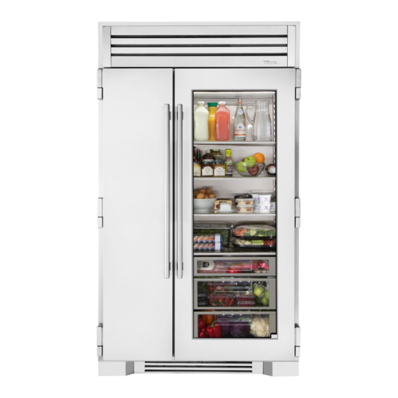
C O N T E N T S SAFETY INFORMATION & OWNERSHIP CABINET SETUP OWNERSHIP SHELVING SAFETY PRECAUTIONS REFRIGERATOR STORAGE DISPOSAL OF OLD REFRIGERATOR FREEZER STORAGE CFC DISPOSAL KICKPLATE INSTALLATION PRIOR TO INSTALLATION REFRIGERATOR / FREEZER OPERATION SITE PREPARATION BASIC ELECTRONIC CONTROL OPERATIONS ELECTRICAL REQUIREMENTS SHOWROOM MODE INSTALLATION PLAN VIEWS... - Page 4 T H E T R U E 4 2 / 4 8 TR-42SBS-SS-B TR-48SBS-SG-SS-B STAINLESS SOLID DOOR STAINLESS SOLID DOOR L U X URY R EF R IG ER AT ION W I T H C OMMER CI A L DN A . Page 4 of 48 T RUE RE S ID E N TI A L 03/31/2022...
-
Page 5: Safety Information & Ownership
S A F E T Y I N F O R M A T I O N & O W N E R S H I P O W N E R S H I P S A F E T Y P R E C A U T I O N S D I S P O S A L O F T H E O L D R E F R I G E R A T O R C F C D I S P O S A L P R E S E R V E T H E M O M E N T... -
Page 6: Ownership
BEF O R E YOU T HR O W AWAY YOUR O L D the delivery freight carrier. True is not responsible for R EF R IG ER AT O R O R F R EE Z ER : damage incurred during shipment. -
Page 7: Prior To Installation
P R I O R T O I N S T A L L A T I O N S I T E P R E P A R A T I O N E L E C T R I C A L R E Q U I R E M E N T S P R E S E R V E T H E M O M E N T ®... -
Page 8: Site Preparation
P R I O R T O I N S T A L L A T I O N SITE PREPAR ATION • Rough Opening dimensions. (See figure 1 and 2) • For FLUSH installations the front face of the unit will be flush with the surrounding cabinets. (See figure 3) •... - Page 9 P R I O R T O I N S T A L L A T I O N TR-42 T OP V IE W F IGUR E 3 – F L U SH IN S TA L L ⁄ "...
- Page 10 P R I O R T O I N S T A L L A T I O N TR-48 T OP V IE W F R ON T V IE W F IGUR E 1 – R OUGH OP ENING F IGUR E 2 –...
- Page 11 P R I O R T O I N S T A L L A T I O N TR-48 T OP V IE W F IGUR E 3 – F L U SH IN S TA L L ⁄ "...
-
Page 12: Electrical Requirements
P R I O R T O I N S T A L L A T I O N F IGUR E 5 ELEC TRIC AL REQUIREMENT S F R ON T V IE W R OUGH OP ENING For all built-in models, the electrical supply should be &... -
Page 13: Installation Plan Views
I N S T A L L A T I O N P L A N V I E W S T R - 4 2 S B S - S S - B T R - 4 8 S B S - S G - S S - B P R E S E R V E T H E M O M E N T ®... -
Page 14: Plan Views
I N S T A L L A T I O N P L A N V I E W S OVER ALL DIMENSIONS – TR-42 T OP V IE W ⁄ " CABINET WIDTH ⁄ " " DOORS OPEN 90º ⁄... - Page 15 I N S T A L L A T I O N P L A N V I E W S OVER ALL DIMENSIONS – TR-42 F R ON T V IE W ⁄ " ⁄ " ⁄ " DOOR HEIGHT SIDE V IE W ⁄...
- Page 16 I N S T A L L A T I O N P L A N V I E W S OVER ALL DIMENSIONS – TR-48 T OP V IE W ⁄ " CABINET WIDTH ⁄ " ⁄ " DOORS OPEN 90º ⁄...
- Page 17 I N S T A L L A T I O N P L A N V I E W S OVER ALL DIMENSIONS – TR-48 F R ON T V IE W 20 " ⁄ " DOOR " HEIGHT GLASS ⁄...
- Page 18 N O T E S Page 18 of 48 T RUE RE S ID E N TI A L 03/31/2022 TEC_TM_065 REV. B ®...
-
Page 19: Installation
I N S T A L L A T I O N U N C R A T I N G A N T I -T I P B R A C K E T I N S T A L L A T I O N L E V E L I N G T H E U N I T J O I N I N G K I T I N S T A L L A T I O N P R E S E R V E T H E M O M E N T... -
Page 20: Uncrating
M AT CH F IGUR E S SHO W N. P R O CEDUR E 1. Inspect the pallet exterior packaging for visible damage. See fig. 1. Follow TRUE’s recommended procedure for accepting deliveries. FIG. 2. Inspect the unit’s exterior for visible damage. - Page 21 I N S T A L L A T I O N UNCR ATING (CONT.) 3. Closely inspect the unit’s interior for damage (e.g., scratches by shelving or damage to the door seal). See fig. 5. NO T E: D O NO T R EMO V E T HE IN T ER IO R PA CK A GING.
- Page 22 I N S T A L L A T I O N UNCR ATING (CONT.) 6. Remove the condensate drain pan. Set the drain pan aside. See fig. 9. 7. Slightly raise the rear leveling leg rollers. Turn the front adjustment screw 1/4-1/2 turn clockwise. See fig.
-
Page 23: Anti-Tip Bracket Installation
CKE T INS TALL ATION 2. Using the bracket as a guide, drill pilot holes into the I N S T A L L A T I O N wall/floor. It is recommended to secure the bracket 1.1) to as many floor joists and wall studs as possible. PROCEDURE ANTI-TIP BR ACKE T INS TALL ATION 3. - Page 24 I N S T A L L A T I O N Anti-Tip Kit Install TR-42SBS-SS-B 42 INCH UNIT T OP V IE W 20 25/32" 528mm 9 9/32" 9 9/32" 236mm 236mm 22 31/32" 24 31/32" 583mm 634mm PROUD INSTALL FLUSH INSTALL ℄...
-
Page 25: Leveling The Unit
I N S T A L L A T I O N LE VELING THE UNIT It is very important that the refrigerator sits level. This will insure that the doors will align and seal properly and that the drain pans will not spill over. P R O CEDUR E 1. -
Page 26: Joining Kit Installation
987036 I N S T A L L A T I O N TRUE RESIDENTIAL REFRIGERATION 5.19.17 AL UPRIG HT ANTI-TIP BR ACKE T INS TALL ATION JOINING KIT INS TALL ATION 2. Using the bracket as a guide, drill pilot holes into the ANTI-TIP BR ACKE T KIT: Kit Sizes: 60"... - Page 27 I N S T A L L A T I O N JOINING KIT INS TALL ATION (CONT.) Kit Sizes: 60" (1524 mm) / 72" (1828.8 mm) / 78" (1981.2 mm) / 90" (2286 mm) P R O CEDUR E 1.
- Page 28 I N S T A L L A T I O N JOINING KIT INS TALL ATION (CONT.) Kit Sizes: 60" (1524 mm) / 72" (1828.8 mm) / 78" (1981.2 mm) / 90" (2286 mm) 7. Install anti-sweat foam end panels on the joined units’...
- Page 29 I N S T A L L A T I O N JOINING KIT INS TALL ATION (CONT.) Kit Sizes: 60" (1524 mm) / 72" (1828.8 mm) / 78" (1981.2 mm) / 90" (2286 mm) 14. Walk the joined units into their final installation location.
- Page 30 N O T E S Page 30 of 48 T RUE RE S ID E N TI A L 03/31/2022 TEC_TM_065 REV. B ®...
-
Page 31: Cabinet Setup
C A B I N E T S E T U P S H E L V I N G R E F R I G E R A T O R S T O R A G E F R E E Z E R S T O R A G E K I C K P L A T E I N S T A L L A T I O N P R E S E R V E T H E M O M E N T ®... -
Page 32: Shelving
C A B I N E T S E T U P SHELVING , BINS , DR AWERS All shelving and door bins come packaged inside the unit. (See Figure 1) FIG. 1. Interior packaging. REFRIG ER ATOR S TOR AG E G L A S S SHELV E S Remove the top foam piece holding the glass shelves. -
Page 33: Freezer Storage
C A B I N E T S E T U P D R AW ER S To remove a drawer, pull drawer forward until it stops. Use a Phillips screw driver to remove the two (2) screws securing the drawer to the slides, then lift the drawer up and out of unit. -
Page 34: Kickplate Installation
C A B I N E T S E T U P KICKPL ATE INS TALL ATION The kickplate is shipped with the unit but not attached to allow access to level the unit. Once the unit is level, the kickplate attaches to the front, bottom of the unit with magnets located on the left and right. -
Page 35: Refrigerator / Freezer Operation
R E F R I G E R A T O R / F R E E Z E R O P E R A T I O N E L E C T R O N I C C O N T R O L O P E R A T I O N S S H O W R O O M M O D E P R E S E R V E T H E M O M E N T ®... -
Page 36: Basic Electronic Control Operations
R E F R I G E R A T O R / F R E E Z E R O P E R A T I O N ELEC TRONIC CONTROL OPER ATIONS UNI T ON / O F F NO T E : W HENE V ER T HE UNI T I S SW I T CHED O F F U SING T HE P O W ER K E Y, T HE W O R D “... - Page 37 R E F R I G E R A T O R / F R E E Z E R O P E R A T I O N TEMPER AT URE AD JUS TMENT (ZONE NAVIG ATION) T HE T EMP ER AT UR E R A NG E IN A To adjust set-points, press ZONE for the appropriate R EF R IG ER AT O R Z ONE I S + 3 2 °F (0 °C) T O compartment, then DOWN or UP key on control panel...
- Page 38 R E F R I G E R A T O R / F R E E Z E R O P E R A T I O N MODE NAVIG ATION The following pages illustrate unique customer • Freezer defrosting functions will convert to a fixed input operations performed at the control panel.
- Page 39 R E F R I G E R A T O R / F R E E Z E R O P E R A T I O N ACCENT LIG HTING S YS TEM All models are equipped with an accent lighting system illuminated when the door is closed, in the DOOR in the refrigerator and or freezer compartment(s).
- Page 40 R E F R I G E R A T O R / F R E E Z E R O P E R A T I O N AL ARM NAVIG ATION (D O OR A JAR AL ARM FE AT URE ON/OFF) All Residential Series units are equipped with a door notification icons will appear and an audible alarm will ajar alarm feature.
- Page 41 R E F R I G E R A T O R / F R E E Z E R O P E R A T I O N NOTIFIC ATION ALERT S The diagrams on these pages illustrate what a customer may see in the LCD if the appliance needs attention. NO T IF IC AT ION A L ER T S NOTIFICATION ALERTS 0°F...
-
Page 42: Showroom Mode
R E F R I G E R A T O R / F R E E Z E R O P E R A T I O N SHOWRO OM MODE When in Showroom Mode all cooling and defrosting functions are disabled, but the lighting system and door ajar alarm system remain operational, and the LCD will show the set-points. -
Page 43: Maintenance, Care & Cleaning
M A I N T E N A N C E , C A R E & C L E A N I N G S T A I N L E S S S T E E L E Q U I P M E N T C A R E A N D C L E A N I N G G E N E R A L M A I N T E N A N C E C O N D E N S A T I O N D A T A T A G... -
Page 44: Stainless Steel Equipment Care & Cleaning
G E N E R A L M A I N T E N A N C E , C A R E & C L E A N I N G S TAINLE SS S TEEL EQUIPMENT C ARE AND CLE ANING NOTE! Do not use any steel wool, STAINLESS STEEL CLEANING AND RESTORATION... - Page 45 G E N E R A L M A I N T E N A N C E , C A R E & C L E A N I N G S TAINLE SS S TEEL EQUIPMENT C ARE AND CLE ANING •...
-
Page 46: General Maintenance
WA R R A N T Y D EPA R T MEN T SER V ICE D EPA R T MEN T Phone: 888-616-8783 Phone: 844-849-6179 Phone: 844-746-9423 info@true-residential.com trueresidentialwarranty@truemfg.com TrueResidentialService@truemfg.com Page 46 of 48 T RUE RE S ID E N TI A L 03/31/2022 TEC_TM_065 REV. -
Page 47: Warranty
DISPLAY PRODUCTS True Residential Products on showroom display that are sold more than 3 years (36 months) from the invoice date to the dealer would carry a 1 year parts and labor warranty, along with an additional 4 year sealed system, parts only warranty. - Page 48 CONTACT US t r u e - r e s i d e n t i a l . c o m 6 3 6 . 2 4 0 . 2 4 0 0 t o l l f r e e 8 8 8 . 6 1 6 . 8 7 8 3 T RUE RE S ID E N TI A L 03/31/2022 TEC_TM_065 REV.
Need help?
Do you have a question about the RESIDENTIAL TR-42SBS-SS-B and is the answer not in the manual?
Questions and answers