
Related Manuals for True TRUE RESIDENTIAL Series


Summary of Contents for True TRUE RESIDENTIAL Series
- Page 1 TRUE RESIDENTIAL ® T R - 3 0 / T R - 3 6 I N S T A L L A T I O N / U S E R G U I D E P R E S E R V E T H E M O M E N T ®...
- Page 2 THANK YOU FOR YOUR PURCHA SE Page ii of 50 December 27, 2019 TEC_TM_009 Rev. B...
- Page 3 INDE X OWNERSHIP, S AFE T Y PRECAUTIONS, DISP O S AL OF OL D REFRIGER ATOR, CFC DISP O S AL 3 - 4 SITE PREPAR ATION, EL ECTRICAL REQUIREMENTS, ANTI - SWE AT FOAM END PANEL S 5 - 8 PL AN V IE W S 9 -16 ANTI -TIP BR ACK E T INSTAL L ATION, L E V ELING THE UNIT, JOINING K IT INSTAL L ATION...
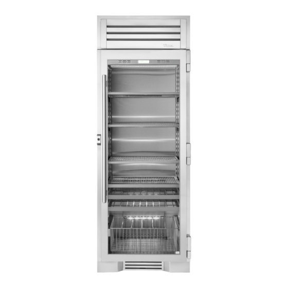
- Page 4 36” FREEZER COLUMN COLUMN COLUMN STAINLESS SOLID DOOR STAINLESS GLASS DOOR STAINLESS SOLID DOOR Commercial refrigeration refined for the home, envied in the industry, and crafted—gorgeously—in America. TEC_TM_009 Rev. B TRUE RESIDENTIAL Page 2 of 50 ® December 31, 2019...
- Page 5 3 - 4 w n e r s h i p a f e t y r e c a u t i O n s i s p O s a l O f t h e e f r i g e r a t O r c f c D i s p O s a l PRESERVE THE MOMENT...
-
Page 6: Safety Precautions
IN D I V IDUA L . M O N E Y W E L L SP EN T. PROPER DISP OSAL OF THE OLD Before you start to install your True Residential ® REFRIG ER ATOR Cabinet, carefully inspect it for freight damage. If... - Page 7 5 - 8 i t e r e p a r a t i O n l e c t r i c a l e q u i r e m e n t s n t i w e a t O a m a n e l s PRESERVE THE MOMENT...
- Page 8 INSTALL (769 mm) N O T E : D I M E N S I O N S M AY VA R Y B Y ± ” TEC_TM_009 Rev. B TRUE RESIDENTIAL Page 6 of 50 ® December 31, 2019...
- Page 9 TR-30 – TOP VIEW TR-30 – FRONT VIEW TR-30 – SIDE VIEW 30 15/32" 30 15/32" 774mm 774mm 27 29/32" 2 9/16" 20 11/16" 2 9/16" 27 29/32" 20 11/16" 65mm 709mm 709mm 525mm 65mm 30" 525mm 36" 762mm 25 25/32" 25 25/32"...
-
Page 10: Electrical Requirement
(844) 849-6226, or emailing trueresidentialparts@truemfg.com. If installing anti-sweat foam end panels, we recommend that a panel be applied to each of the units being joined together. TEC_TM_009 Rev. B TRUE RESIDENTIAL Page 8 of 50 ® December 31, 2019... - Page 11 9 - 16 P L A N V I E W S t r - 3 0 / t r - 4 2 t r - 3 0 / t r - 4 8 t r - 3 0 / t r - 3 0 t r - 3 0 / t r - 3 0 / t r - 3 0 t r - 3 6 / t r - 3 6 t r - 3 6 / t r - 3 0...
- Page 12 PL AN VIEW 774mm 25 25/32" 655mm 27 29/32" 2 9/16" FLUSH INSTALL 65mm 709mm 72 1/32" 25 25/32" 1829mm 655mm 83 15/16" 2132mm 3 15/16" 100mm TEC_TM_009 Rev. B TRUE RESIDENTIAL Page 10 of 50 ® December 31, 2019...
- Page 13 TR-30 / TR-48 23 25/32" FLUSH OPENING DIMENSIONS PROUD OPENING DIMENSIONS 604mm PROUD INSTALL Width Depth Height Width Depth Height 781/4" " 84 1/4" 773/4" " 84" 25/32 25/32 " N O T E : D I M E N S I O N S M AY VA R Y B Y ± TR-48,30D ROUG H OPENING &...
- Page 14 PL AN VIEW 30 15/32" 774mm 25 25/32" 27 29/32" 655mm 2 9/16" FLUSH INSTALL 65mm 709mm 60 1/32" 25 25/32" 1525mm 655mm 83 15/16" 2132mm 3 15/16" 100mm TEC_TM_009 Rev. B TRUE RESIDENTIAL Page 12 of 50 ® December 31, 2019...
- Page 15 TR-30REF,30FRZ,30DZW TR-30 / TR-30 / TR-30 FLUSH OPENING DIMENSIONS PROUD OPENING DIMENSIONS Width Depth Height Width Depth Height 23 25/32" 604mm 901/4" " 84 1/4" 89 3/4" " 84" 25/32 25/32 PROUD INSTALL TR-30REF,30DZW ROUG H OPENING & ELEC TRIC AL ARE A FLUSH VS .
- Page 16 72 1/4" FLUSH INSTALL PL AN VIEW 30 15/32" 774mm 27 29/32" 2 9/16" 709mm 65mm 72 1/32" 25 25/32" 1829mm 655mm 83 15/16" 2132mm 3 15/16" 100mm TEC_TM_009 Rev. B TRUE RESIDENTIAL Page 14 of 50 ® December 31, 2019...
- Page 17 TR-36REF / TR-30REF FLUSH OPENING DIMENSIONS PROUD OPENING DIMENSIONS Width Depth Height Width Depth Height 661/4" " 84 1/4" 653/4" " 84" 25/32 25/32 " N O T E : D I M E N S I O N S M AY VA R Y B Y ± TR-36REF,30REF FLUSH VS .
- Page 18 TEC_TM_009 Rev. B TRUE RESIDENTIAL Page 16 of 50 ® December 31, 2019...
- Page 19 17 - 26 n t i r a c k e t n s t a l l a t i O n e v e l i n g t h e n i t O i n i n g n s t a l l a t i O n PRESERVE THE MOMENT ®...
- Page 20 236mm 9 9/32" 236mm 24 31/32" 22 31/32" 634mm 583mm FLUSH INSTALL PROUD INSTALL ℄ = Center Line –-– = Bracket Location *Dimensions may vary by ±1/8” TEC_TM_009 Rev. B TRUE RESIDENTIAL Page 18 of 50 ® December 31, 2019...
- Page 21 Anti-Tip Kit Install TR-42SBS-SS-B 42 INCH UNIT 20 25/32" 528mm 9 9/32" 9 9/32" 236mm 236mm 22 31/32" 24 31/32" 583mm 634mm PROUD INSTALL FLUSH INSTALL ℄ = Center Line Anti-Tip Kit Install TR-48SBS-SS –-– = Bracket Location *Dimensions may vary by ±1/8” 48 INCH UNIT 23 25/32"...
-
Page 22: Leveling The Unit
STEP 3. Adjust the rear using a 7/16" socket and ratchet. Turn clockwise to raise the rear of the unit. REAR LEG ADJUSTMENT FRONT LEG ADJUSTMENT L EG A D JU S T MEN T S TEC_TM_009 Rev. B TRUE RESIDENTIAL Page 20 of 50 ® December 31, 2019... - Page 23 5.18 SD TR-30 60"/90" JOINING KIT INS TALL ATION KIT INCLUDES TOOLS REQUIRED A. 60" Grill or 90" Grill • Phillips screwdriver B. Anti-sweat foam end panels • Power drill C. Pop rivets • 3/32" drill bit D. Lower joining bracket •...
- Page 24 Image 6. NOTE: ALL HARDWARE YOU REMOVE WILL BE USED TO INSTALL THE NEW RAIN SHIELD. NOTE: REPEAT STEPS 1-7 FOR EACH TR-30 UNIT YOU ARE INSTALLING. TEC_TM_009 Rev. B TRUE RESIDENTIAL Page 22 of 50 ® December 31, 2019...
- Page 25 STEP 7 Remove the two 1/4" screws that hold the magnet bracket for the louver grill on the left right side of the units that are joining together. Remove both screws and set the bracket aside. This bracket will NOT reinstall with this application. NOTE: REINSTALL THE SCREWS THAT WERE HOLDING THE BRACKET.
- Page 26 Image 11a, 11b & 11c. NOTE: IT'S RECOMMENDED TWO OR MORE PEOPLE ASSIST SETTING THE RAIN SHIELD IN PLACE WHILE IT'S BEING SECURELY MOUNTED. TEC_TM_009 Rev. B TRUE RESIDENTIAL Page 24 of 50 ® December 31, 2019...
- Page 27 STEP 12 Route the reed switch wires through the P-clips and bushings in the new grill. Image 12a, 12b & 12c. NOTE: P-CLIPS WILL ONLY BE USED ON EACH END OF THE NEW GRILL NOT IN THE CENTER (APPLIES TO 90 INCH ONLY). STEP 13 Reconnect door switch wires to reed switch (it 12 a...
- Page 28 TEC_TM_009 Rev. B TRUE RESIDENTIAL Page 26 of 50 ® December 31, 2019...
- Page 29 27 - 34 R E F R I G E R A T O R A N D F R E E Z E R a s i c l e c t r O n i c p e r a t i O n s h O w r O O m O D e PRESERVE THE MOMENT...
- Page 30 CEL SIU S, IN MO S T C A SE S FA HR ENHEI T R E A DING S A R E SHO W N IN T HI S M A NUA L . TEC_TM_009 Rev. B TRUE RESIDENTIAL Page 28 of 50 ®...
-
Page 31: Temperature Adjustment
TEMPER ATURE ADJUS TMENT To adjust set-point, press DOWN or UP key on control panel in multiple key strokes until the desired set-point is achieved. Each key stroke equals a one degree change and is accompanied by an audible beep. When the desired set-point is reached wait 5 seconds until display resumes “HOME”... -
Page 32: Mode Navig Ation
MODE ENDS ON NEXT DOOR TEMPERATURE ºF MODE OPENING VACATION MODE SERVICE REPORT NO SERVICE REQUIRED MODE EXIT Return from Service Screen SERVICE REPORT 38°F EXIT MODE Back to Home Screen TEC_TM_009 Rev. B TRUE RESIDENTIAL Page 30 of 50 ® December 31, 2019... - Page 33 ACCENT LIG HTING SYS TEM All models are equipped with an accent lighting system in the refrigerator and or freezer compartment(s). To energize the accent lighting system, press the LIGHT key, and navigate to the corresponding compartment, DOOR or ON will appear in the LCD indicating the accent lights are enabled. With the accent lighting system ON, the LED’s will be energized and stay illuminated when the door is closed, in the DOOR position the lighting system will only be energized with the door opening.
- Page 34 DOOR ALARM IS ON 38°F EXIT ALARM refrigerator door ajar DOOR ALARM IS ON DOOR ALARM IS OFF EXIT EXIT ALARM DOOR ALARM IS OFF EXIT ALARM 38°F Screen TEC_TM_009 Rev. B TRUE RESIDENTIAL Page 32 of 50 ® December 31, 2019...
-
Page 35: Notific Ation Alert S
NOTIFIC ATION ALERT S The diagrams on these pages illustrate what a customer may see in the LCD if the appliance needs attention. NO T IF IC AT ION A L ER T S LIGHT ALARM MODE 38°F 38°F defrost •... -
Page 36: Showroom Mode
Showroom Mode O f f EfRigER ato R REE zER Showroom Mode O f f EfRigER ato R REE zER Showroom Mode On EfRigER ato R REE zER TEC_TM_009 Rev. B TRUE RESIDENTIAL Page 34 of 50 ® December 31, 2019... -
Page 37: D U A L Z O N E
35 - 42 D U A L Z O N E a s i c l e c t r O n i c p e r a t i O n s h O w r O O m O D e PRESERVE THE MOMENT ®... -
Page 38: Ba Sic Elec Tronic Control Oper Ations
CEL SIU S, IN MO S T C A SE S FA HR ENHEI T R E A DING S A R E SHO W N IN T HI S M A NUA L . TEC_TM_009 Rev. B TRUE RESIDENTIAL Page 36 of 50 ®... - Page 39 TEMPER ATURE ADJUS TMENT To adjust set-point, press the ZONE button to highlight the zone for adjustment. Once the zone is highlighted, press DOWN or UP key on the control panel in multiple key strokes until the desired set-point is achieved. Each key stroke equals a one degree change and is accompanied by an audible beep.
- Page 40 TEMPERATURE ºF MODE OPENING VACATION MODE SERVICE REPORT NO SERVICE REQUIRED MODE EXIT Return from Service Screen SERVICE REPORT 55°F EXIT MODE 45°F Back to Home Screen TEC_TM_009 Rev. B TRUE RESIDENTIAL Page 38 of 50 ® December 31, 2019...
-
Page 41: Color Chang E
ACCENT LIG HTING SYS TEM All models are equipped with an accent lighting system in the refrigerator and or freezer compartment(s). To change the accent lighting color, press the LIGHT key once until you see “CHANGE COLOR” press the LIGHT button once again to start . - Page 42 45°F door ajar DOOR ALARM IS ON DOOR ALARM IS OFF EXIT EXIT ALARM DOOR ALARM IS OFF 55°F EXIT ALARM 45°F Back to Home Screen TEC_TM_009 Rev. B TRUE RESIDENTIAL Page 40 of 50 ® December 31, 2019...
- Page 43 NOTIFIC ATION ALERT S The diagrams on these pages illustrate what a customer may see in the LCD if the appliance needs attention. NO T IF IC AT ION A L ER T S 55°F MODE LIGHT ALARM ZONE 45°F 55°F 45°F defrost...
- Page 44 Showroom Mode O f f EfRigER ato R REE zER Showroom Mode O f f EfRigER ato R REE zER Showroom Mode On EfRigER ato R REE zER TEC_TM_009 Rev. B TRUE RESIDENTIAL Page 42 of 50 ® December 31, 2019...
- Page 45 43 - 46 h e l v i n g e f r i g e r a t O r t O r a g e r e e z e r t O r a g e e m O v i n g t h e O O r s i c k l a t e...
-
Page 46: Refrigerator Storage
Phillips screw driver. TEC_TM_009 Rev. B TRUE RESIDENTIAL Page 44 of 50 ®... -
Page 47: Freezer S Tor Ag E
FREEZER S TOR AG E W IR E SHELV E S Remove the top foam piece holding the wire shelves. Carefully remove shelves and set aside. Remove all other packing material. To install, insert wire shelf into the shelf standards on the back wall, with the front tilted upward, and then lower the front until it stops. - Page 48 TEC_TM_009 Rev. B TRUE RESIDENTIAL Page 46 of 50 ® December 31, 2019...
- Page 49 47 - 50 t a i n l e s s t e e l q u i p m e n t a r e a n D l e a n i n g e n e r a l a i n t e n a n c e O n D e n s a t i O n a t a...
-
Page 50: S Tainle Ss S Teel Equipment C Are And Cle Aning
® or Simple Green Industrial Cleaner & Degreaser) are ® excellent for removal of grease, fatty acids, blood and burnt-on foods on all surfaces. TEC_TM_009 Rev. B TRUE RESIDENTIAL Page 48 of 50 ® December 31, 2019... -
Page 51: General Maintenance
CONTAC T US CUSTOMER SERVICE WARRANTY DEPARTMENT SERVICE DEPARTMENT Phone: 888-616-8783 Phone: 844-849-6179 Phone: 844-746-9423 www.true-residential.com trueresidentialwarranty@truemfg.com service@truemfg.com December 31, 2019 Page 49 of 50 TEC_TM_009 Rev. B... - Page 52 THREE-YEAR PARTS & LABOR WARRANTY *For units purchased after Feb 1, 2013. TRUE warrants to the original purchaser of every new TRUE refrigerated unit, the cabinet and all parts thereof, to be free from defects in material or workmanship under normal and proper use and maintenance as specified by TRUE and upon proper installation and start-up in accordance with the instruction packet supplied with each TRUE unit.
- Page 53 TEC_TM_009 Rev. B December 27, 2019 Page 49 of 50...
- Page 54 CONTACT US w w w.t r ue -r e siden tial.com toll free (8 8 8)616 - 878 3 TP · MISC_2248 · 6.19 212530 Page 50 of 50 December 27, 2019 TEC_TM_009 Rev. B...
Need help?
Do you have a question about the TRUE RESIDENTIAL Series and is the answer not in the manual?
Questions and answers