Subscribe to Our Youtube Channel
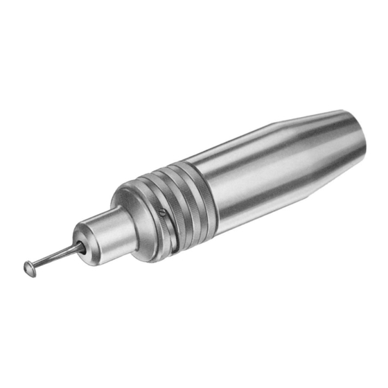
Summary of Contents for Braun Craniotome GB265R
- Page 1 Aesculap Power Systems Service Manual Craniotome GB265R, GB268R and Macro Craniotome GB299 Service-Manual Craniotom GB265R, GB268R und Makro-Craniotom GB299...
- Page 2 GB299801 TA003323 GC303R GB299207 GB299204 TA005581 TA003323 (1x) GB266203 TA005803 GB299208 TA003904 GB299805 TA005761 GB299209 GB299205 TA005799 GB299203 TA 005 801 TA003323 (3x) TA005761 GB299202 GB131202 TA005800 GB125312 TA003189 TA004018...
- Page 3 GB115801...
- Page 4 Aesculap Power Systems Craniotome GB265R, GB268R and Macro Craniotome GB299 Copyright information General advisory Copyright© 2006 This service manual contains illustrations and explanations. Each Aesculap AG & Co. KG® explanation covers the following: modes of operation, spare parts list, All rights reserved 08/06 assembly, disassembly, functionality test, and the section tools/devices (if applicable).
-
Page 5: Table Of Contents
! Operate craniotome GB265R, GB268R and GB299 with authentic 2.1 Tools........................3 Aesculap accessories only. 2.2 Auxiliary materials..................3 ! To avoid damage to the product, do not knock craniotome GB265R, 2.3 Supplies ......................3 GB268R and GB299 against hard objects. Expendable parts/Replacement parts............4 Designation of the craniotome elements .......... -
Page 6: Expendable Parts/Replacement Parts
GB266 ! Check all glued joints for firm seating. ! Spray through craniotome GB265R, GB268R and GB299 with oil spray GB149. 5. Basic preparations and maintenance 5.2 Maintenance In order to ensure reliable operation, Aesculap recommends maintenance after every 300 reprocessing cycles or at least once a year. -
Page 7: Troubleshooting List
6. Troubleshooting list Malfunction Finding Cause Remedy Cutter not turning Drive power not transferred to Driver broken Replace driver TA005387 cutter Support foot cannot be coupled Cutter tip does not hit counter Support foot bent Replace support foot support Do not bend – risk of breakage! Marks on surface or borehole Adapter surface damaged Level the surfaces... -
Page 8: Disassembling
Aesculap Power Systems Craniotome GB265R, GB268R and Macro Craniotome GB299 7. Disassembling 7.4 Disassembling the housing (GB299) ! Remove borehole circlip TA005803. ! Unscrew headless screw TA005761 from housing GB299202. ! Remove spindle complete from housing GB299202. 7.1 Disassembling the support foot ! Unscrew clamping screw GB115801 from housing GB299202. -
Page 9: Assembling
8. Assembling 8.4 Pre-assembling the spindle (GB299) ! Install steel ball TA003323 in spindle GB299805. ! Position clamping sleeve GB299204 on spindle GB299805. ! Install compression spring TA005581 on spindle GB299805. 8.1 Preparations ! Apply Loctite 640 on slotted nut GB299207 and screw the nut into ! Rethread every thread, using a tapper. -
Page 10: Postmaintenance
Aesculap Power Systems Craniotome GB265R, GB268R and Macro Craniotome GB299 10. Parts list Assembling support foot GB266M ! Insert 3 steel balls TA003323. ! Insert compression spring TA005799 and sleeve GB299303 in housing GB299801. 10.1 GB265R ! Apply Loctite 222 on headless screw TA005761 and install the screw. -
Page 11: Gb268R
10.2 GB268R 10.3 GB299 Art. no. Designation Art. no. Designation GB266R Turnable Dura guard for GB265R GB125110 Lever upper part (blank) and GB299 GB299206 Bearing bush GB298R Dura guard sleeve for Craniotome TA003323 Steel ball 2 mm NR (x4) GB299 TA003904 Lock washer GB266201... - Page 12 Aesculap Power Systems Craniotom GB265R, GB268R und Makro-Craniotom GB299 Urheberrechtliche Aspekte Grundlegende Hinweise Copyright© 2006 Dieses Service-Manual enthält Darstellungen und Erläuterungen. Die Aesculap AG & Co. KG® Erläuterungen enthalten jeweils die Funktionsweise, Ersatzteilliste, Mon- Alle Rechte vorbehalten 08/06 tage, Demontage, Funktionsprüfung und ggf. das Kapitel Werkzeuge/Vor- richtungen.
-
Page 13: Sichere Handhabung
1. Sichere Handhabung Inhaltsverzeichnis Sichere Handhabung ..................11 Werkzeuge, Hilfsmittel, Betriebsstoffe ..........11 ! Craniotom GB265R, GB268R und GB299 nur mit Original-Aesculap- 2.1 Werkzeuge .....................11 Zubehör betreiben. 2.2 Hilfsmittel ......................11 ! Um Beschädigungen zu vermeiden, Craniotom GB265R, GB268R und 2.3 Betriebsstoffe ....................11 GB299 nicht auf harten Gegenständen aufklopfen. -
Page 14: Verschleißteile/Ersatzteile
Aesculap Power Systems Craniotom GB265R, GB268R und Makro-Craniotom GB299 3. Verschleißteile/Ersatzteile Oberflächen prüfen ! Oberflächen prüfen auf: – Druckstellen – Flecken Bezeichnung Art.-Nr. – scharfe Kanten Radialkugellager 8 x 16 x 6 ALSI TA005800 – Kleberückstände (2 Stück) Kerbstift DIN 1473 1,2 x 5 NR TA005387 Anschlüsse prüfen Sicherungsscheibe... -
Page 15: Fehler Erkennen Und Beheben
6. Fehler erkennen und beheben Störung Erkennung Ursache Behebung Fräser dreht nicht Antrieb wird nicht auf Fräser Mitnehmer gebrochen Mitnehmer TA005387 tauschen übertragen Stützfuß lässt sich nicht kuppeln Fräserspitze trifft Gegenlager Stützfuß verbogen Stützfuß tauschen. nicht Nicht biegen - Bruchgefahr! Marken auf Fläche oder Bohrung Aufnahmefläche beschädigt Flächen egalisieren... -
Page 16: Demontage
Aesculap Power Systems Craniotom GB265R, GB268R und Makro-Craniotom GB299 7. Demontage 7.4 Gehäuse demontieren (GB299) ! Bohrungssprengring TA005803 entfernen. ! Schaftschraube TA005761 aus Gehäuse GB299202 schrauben. ! Spindel komplett aus Gehäuse GB299202 entfernen. 7.1 Stützfuß demontieren ! Knebelschraube GB115801 von Gehäuse GB299202 schrauben. ! Schraube TA004018 aus Gehäuse GB299202 schrauben. -
Page 17: Montage
8. Montage 8.4 Spindel vormontieren (GB299) ! Stahlkugel TA003323 in Spindel GB299805 einbringen. ! Spannhülse GB299204 auf Spindel GB299805 stecken. ! Druckfeder TA005581 auf Spindel GB299805 stecken. 8.1 Vorarbeiten ! Schlitzmutter GB299207 mit Loctite 640 versehen und mit Schlitzmut- ! Alle Gewinde mit Gewindeschneider nachschneiden. terdreher in Spindel GB299805 schrauben. -
Page 18: Stützfuß Gb266M Montieren
Aesculap Power Systems Craniotom GB265R, GB268R und Makro-Craniotom GB299 10. Stückliste Stützfuß GB266M montieren ! 3 Stahlkugeln TA003323 einsetzen. ! Druckfeder TA005799 und Hülse GB299303 in Gehäuse GB299801 set- zen. 10.1 GB265R ! Schaftschraube TA005761 mit Loctite 222 versehen und einschrauben. ! Gleitscheiben GB266203 und Passscheiben TA008768 auf Einschraub- Art.-Nr. -
Page 19: Gb268R
10.2 GB268R 10.3 GB299 Art.-Nr. Bezeichnung Art.-Nr. Bezeichnung GB266R Drehbarer Duraschutz zu GB265R GB125110 Hebel-Oberteil (Rohteil) und GB299 GB299206 Lagerbüchse GB298R Duraschutzhülse zu Craniotom TA003323 Stahlkugel 2 mm NR (4 Stück) GB299 TA003904 Sicherungsscheibe GB266201 Stützfußhülse TA004018 Zylinderschraube DIN 84 GB266202 Einschraubbüchse M 2,6 x 6,0... - Page 20 CE marking according to directive 93/42/EEC CE-Kennzeichnung gemäß Richtlinie 93/42/EWG Technical alterations reserved Technische Änderungen vorbehalten Aesculap AG & Co. KG Am Aesculap-Platz 78532 Tuttlingen Germany Phone +49 7461 95-0 +49 7461 95-2600 TA-Nr. 011238 08/06 Änd.-Nr. YYY/Y/Y www.aesculap.de...


Need help?
Do you have a question about the Craniotome GB265R and is the answer not in the manual?
Questions and answers