Table of Contents
Advertisement
Quick Links
Advertisement
Table of Contents

Subscribe to Our Youtube Channel
Related Manuals for ADJ FOCUS SPOT 6Z


Summary of Contents for ADJ FOCUS SPOT 6Z
- Page 1 FOCUS SPOT 6Z User Manual...
- Page 2 Products, LLC brands and product names are trademarks or registered trademarks of their respective companies. ADJ Products, LLC and all affiliated companies hereby disclaim any and all liabilities for property, equipment, building, and electrical damages, injuries to any persons, and direct or indirect economic...
-
Page 3: Table Of Contents
TABLE OF CONTENTS Introduction Limited Warranty (USA Only) Features | Warranty Registration Safety Precautions Installation Maintenance Guidelines Overview DMX Set Up DMX Addressing DMX Traits System Menu Primary-Secondary Set Up Dimmer Modes Gobo Replacement Gobos Color Wheels Multi Unit Power Linking | Trouble Shooting | Cleaning Specifications... -
Page 4: Introduction
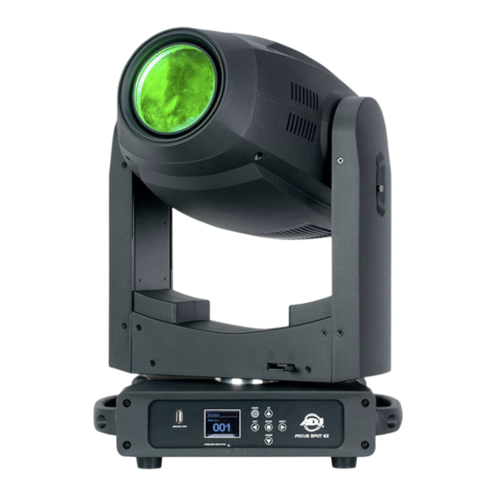
Do not return this unit to your dealer without first contacting customer support. Introduction: The Focus Spot 6Z is a DMX intelligent, moving head LED fixture. This fixture can be used in stand alone mode, or connected in a Primary-Secondary configuration. The fixture comes equipped with motorized focus and zoom, 6 different dimming options, and 3 DMX channel modes (21, 25, or 29 channels). -
Page 5: Limited Warranty (Usa Only)
LIMITED WARRANTY (USA ONLY) A. ADJ Products, LLC hereby warrants, to the original purchaser, ADJ Products, LLC products to be free of manufacturing defects in material and workmanship for a prescribed period from the date of purchase (see specific warranty period on reverse). This warranty shall be valid only if the product is purchased within the United States of America, including possessions and territories. -
Page 6: Features | Warranty Registration
Omega Bracket (x2) WARRANTY REGISTRATION The Focus Spot 6Z carries a 2 year limited warranty. Please fill out the enclosed warranty card to validate your purchase. All returned service items, whether under warranty or not, must be freight pre- paid and accompanied by a return authorization (R.A.) number. The R.A. number must be clearly writ- ten on the outside of the return package. -
Page 7: Safety Precautions
SAFETY PRECAUTIONS PROTECTION CLASS 1 - FIXTURE MUST BE PROPERLY GROUNDED. THERE ARE NO USER SERVICEABLE PARTS INSIDE THIS UNIT. DO NOT ATTEMPT ANY REPAIRS YOURSELF, AS DOING SO WILL VOID YOUR MANUFACTURER’S WARRANTY. DAMAGES RESULTING FROM MODIFICATIONS TO THIS FIXTURE AND/OR THE DISREGARD OF SAFETY INSTRUCTIONS AND GUIDELINES IN THIS MANUAL VOID THE MANUFACTURER’S WARRANTY AND ARE NOT SUBJECT TO ANY WARRANTY CLAIMS AND/OR REPAIRS. -
Page 8: Installation
INSTALLATION DO NOT INSTALL THE FIXTURE IF YOU ARE NOT QUALIFIED TO DO SO! Fixture MUST be installed following all local, national, and country commercial electrical and con- struction codes and regulations. Before rigging/mounting a single fixture to any metal truss/structure or placing the fixture(s) on any surface, a professional equipment installer MUST be consulted to determine if the metal truss/ structure or surface is properly certified to safely hold the combined weight of the fixture(s), clamps, cables, and accessories. - Page 9 LEDs. This issue is not specific only to ADJ lighting fixtures, but rather it is a common issue with lighting fix- tures from all manufacturers. Although there is no true way to fully prevent this issue from happening, the guidelines below can reduce the risk of potential damage.
- Page 10 INSTALLATION Screw one clamp into each Omega bracket using an M12 screw and nut. Insert the quick-lock fas- teners of the Omega holders into the respective holes on the bottom of the unit. Tighten the quick- lock fasteners fully clockwise. Pull the safety cable through the openings located on the base plate and over the trussing system or a safe fixation spot.
- Page 11 INSTALLATION NOTICE: The maximum ambient operational temperature for this lighting fixture is 113˚ F (45˚ C). Do not place this lighting fixture in an enviroment where the temperatures exceed this value. This will allow the fixture to run at its best and help prolong the fixture life. The unit is fully operational in three different mounting positions: hanging upside-down from the ceil- ing or trussing, sideways on trussing, or set on a flat level surface.
-
Page 12: Maintenance Guidelines
Regular inspections are recommended to ensure proper function and extended life. There are no user serviceable parts inside this fixture. Please refer all other service issues to an authorized ADJ service technician. Should you need any spare parts, please order genuine parts from your local ADJ dealer. -
Page 13: Overview
OVERVIEW 1. Service Port 11. Power In 2. Display Screen 12. Fuse T5A/250V 3. Left Button 13. Net In 4. Down Button 14. Net Out 5. Enter Button 15. Safety Cable Attachment Point 6. Right Button 16. 5-pin DMX In 7. -
Page 14: Dmx Set Up
DMX SET UP DMX-512: DMX is short for Digital Multiplex. This is a universal protocol used as a form of commu- nication between intelligent fixtures and controllers. A DMX controller sends DMX data instructions from the controller to the fixture. DMX data is sent as serial data that travels from fixture to fixture via the DATA “IN”... - Page 15 XLR connector of the last unit in your daisy chain to terminate the line. Using a cable terminator (ADJ part number Z-DMX/T) will reduce the risk of erratic behavior. 5-Pin XLR DMX Connectors. Some manufacturers use 5-pin DMX-512 data cables for DATA trans- mission in place of 3-pin.
-
Page 16: Dmx Addressing
DMX ADDRESSING All fixtures should be given a DMX starting address when using a DMX controller, so the correct fix- ture responds to the correct control signal. This digital starting address is the channel number from which the fixture starts to “listen” to the digital control signal sent out from the DMX controller. The assignment of this starting DMX address is achieved by setting the correct DMX address on the digi- tal control display on the fixture. -
Page 17: Dmx Traits
DMX TRAITS CHANNEL FUNCTION VALUES BASIC STANDARD Pan Movement, 8-bit 000 - 255 Pan Fine, 16-bit 000 - 255 Tilt Movement, 8-bit 000 - 255 Tilt Fine, 16-bit 000 - 255 Color Wheel 1 000 - 015 Open / white 016 - 031 032 - 047 Orange... - Page 18 DMX TRAITS CHANNEL FUNCTION VALUES BASIC STANDARD Gobo 1, Continuous Rotation (continued) 070 - 079 Gobo 7 080 - 094 Gobo 1 Shake, slow to fast 095 - 109 Gobo 2 Shake, slow to fast 110 - 124 Gobo 3 Shake, slow to fast 125 - 139 Gobo 4 Shake, slow to fast 140 - 154...
- Page 19 DMX TRAITS CHANNEL FUNCTION VALUES BASIC STANDARD Gobo 2 Rotation 000 - 127 Indexing 128 - 189 Clockwise, fast to slow 190 - 193 No rotation 194 - 255 Counter-clockwise, slow to fast Shutter, Strobe 000 - 031 No function (shutter closed) 032 - 063 Shutter open 064 - 095...
- Page 20 DMX TRAITS CHANNEL FUNCTION VALUES BASIC STANDARD Zoom Fine Indexing 000 - 255 Iris 000 - 191 Indexing 192 - 223 Pulse Open, slow to fast 224 - 255 Pulse Close, fast to slow Frost Filter 1, 0% to 100% 000 - 255 Frost Filter 2, 0% to 100% 000 - 255...
- Page 21 DMX TRAITS CHANNEL FUNCTION VALUES BASIC STANDARD Dim Curves 000 - 020 Linear 021 - 040 Square 041 - 060 Inv. Squa 061 - 080 S. Curve 081 - 255 No function Pan/Tilt Speed, maximum to minimum 000 - 255 LED Refresh Rate 000 - 010 Default LED Refresh Rate...
- Page 22 DMX TRAITS CHANNEL FUNCTION VALUES BASIC STANDARD LED Refresh Rate (continued) 1170 Hz 1180 Hz 1190 Hz 1210 Hz 1220 Hz 1230 Hz 1240 Hz 1250 Hz 1260 Hz 1270 Hz 1280 Hz 1290 Hz 1300 Hz 1310 Hz 1320 Hz 1330 Hz 1340 Hz 1350 Hz...
- Page 23 DMX TRAITS CHANNEL FUNCTION VALUES BASIC STANDARD LED Refresh Rate (continued) 5000 Hz 6000 Hz 10,000 Hz 15,000 Hz 20,000 Hz 25,000 Hz Disable LED Refresh Rate Function 080 - 089 Enable blackout while pan/tilt moving 090 - 099 Disable blackout while pan/tilt moving 100 - 109 Enable blackout while color changing 110 - 119...
-
Page 24: System Menu
SYSTEM MENU CONTROL PANEL The fixture includes an easy to navigate system menu control panel display where all necessary set- tings and adjustments can be made. See image below for reference. During normal operation, pressing the MENU button once will access the fixture’s main menu. Once in the main menu, you can navigate through the different functions and access the sub-menus with the UP and DOWN buttons. - Page 25 SYSTEM MENU A001 - Axxx Set Address Basic (21-ch) DMX Channel Mode Standard (25-ch) DMX SETTINGS Extended (29-ch) Hold Last No DMX Status Blackout Manual Primary On / Off Secondary On / Off Pan Degree 540 / 630 On / Off Pan Invert On / Off Tilt Invert...
- Page 26 SYSTEM MENU Gamma Yes / No Reset All Motors Yes / No Pan/Tilt Reset Reset Motors Yes / No Effect Reset Yes / No Shutter Reset PERSONALITY (continued) 1 - 10 Intensity Yes / No Display Invert Display Screen Saver Delay Off - 10min Key Lock Off / On...
- Page 27 SYSTEM MENU Speed 000 - 255 Program 6 INTERNAL Fade 000 - 255 PROGRAMS Speed 000 - 255 (continued) Program 7 Fade 000 - 255 Lifetime fixture run Power On Time time, non resettable. Fixture Life Time Fixture run time since P-On Time-R last reset.
-
Page 28: Primary-Secondary Set Up
PRIMARY-SECONDARY SET UP This function allows you to link units together to run in a Primary-Secondary set-up, in which one unit will act as the controlling unit and the others will react to the controlling unit’s built-in programs. Any unit can be configured to act as a Primary or as a Secondary, but only one unit in a given sys- tem can be programmed to act as the Primary. -
Page 29: Dimmer Modes
DIMMER MODES DIMMER 100% Time (ms) 0 Sec Rise Time Down Time 0 sec Fade Time 1 sec Fade Time Dimming Curve Ramp Effect Rise Time (ms) Down Time (ms) Rise Time (ms) Down Time (ms) Standard (default) Stage 1100 1540 1660 1180... -
Page 30: Gobo Replacement
GOBO REPLACEMENT This unit features interchangeable gobos. Proceed with caution when changing gobos, as gobos are fragile and can be easily bent, scratched, or otherwise damaged. Caution! Never open the unit when in use. Always disconnect the main power before attempt- ing to change the gobos. - Page 31 GOBO REPLACEMENT 3. Gently push the gobo holder upwards from below (left). When the silver part of the gobo holder clears the face of the gobo wheel, gently grasp the black geared portion of the gobo holder with your fingers and pull the gobo holder away from the gobo wheel (right). The gobo holder should come away easily.
- Page 32 GOBO REPLACEMENT 6. Place the new gobo in the gobo holder with the black side facing downward. Re-install the retain- ing spring with the un-bent end of the spring in contact with the gobo. UN-BENT TIP OF SPRING 7. Turn the gobo holder over so that the black geared side is facing you. Rotate the geared portion of the gobo holder until the mark on the face of the geared portion is aligned with the clip of the gobo holder.
- Page 33 GOBO REPLACEMENT 9. Making sure that the mark on the geared portion of the gobo holder is still aligned with the gobo holder clip, insert the clip of the gobo holder onto the attachment point on the gobo wheel. You should hear an audible click as the gobo holder snaps into place.
-
Page 34: Gobos
GOBOS... -
Page 35: Color Wheels
COLOR WHEELS... - Page 36 MULTI UNIT POWER LINKING With this feature you can connect the fixtures to one another using the power cable input and output sockets. NOTE: USE CAUTION WHEN POWER LINKING OTHER FIXTURES AS THE POWER CONSUMPTION OF OTHER MODEL FIXTURES MAY EXCEED THE MAX POWER OUTPUT ON THIS FIXTURE! CHECK SILK SCREEN FOR MAX AMPS.
- Page 37 DOWNLOAD FIXTURE SOFTWARE TO PC ONLY! (NO MAC SUPPORT) PLEASE CONTACT ADJ CUSTOMER SERVICE FOR FURTHER INFORMATION. 1. Contact ADJ customer service to obtain the updated software, and download the software to a USB flash drive. In order to minimize the risk of downloading the incorrect software to your device, make sure that the desired update files are the only files on the USB flash drive.
-
Page 38: Multi Unit Power Linking | Trouble Shooting | Cleaning
DIMENSIONAL DRAWINGS Drawings may not be shown to scale. -
Page 39: Specifications
Pan/Tilt: • Various strobe speeds • USB firmware update port • Pan: 540/630 degrees • (2) Two Focus Spot 6Z fit inside the DRC MHX road case • Tilt: 270 degrees • 16-bit fine pan & tilt Color Wheels: • Pan & Tilt locks •...
Need help?
Do you have a question about the FOCUS SPOT 6Z and is the answer not in the manual?
Questions and answers