Advertisement
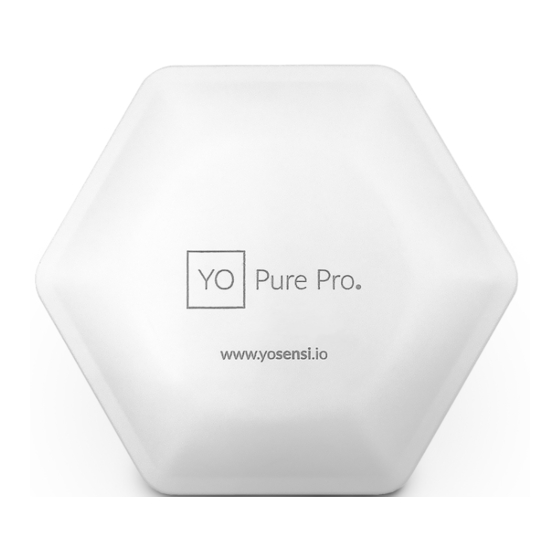
Pure Pro
Quick Installation Guide
I. The device can be powered via USB-C connector, external power supply, or in the
absence of those, from Li-Ion 18650 batteries.
Below is a description of how to connect each of these power supply methods:
1. Via USB-C connector
Plug the 5V USB-C cable into the socket on the enclosure. If the LED indicating
the status of the device/radio lights up, it means that the device has been
successfully connected to the power supply.
2. Power supply 6 - 30 VDC or 5 - 21 VAC
Remove the protective cap which is on the bottom of the enclosure to access
the socket on the device. Screw wires from external power supply into the plug
part of the connector. Then plug it into the socket located on the bottom of the
device. If the device/radio status LED lights up, it means that the device has been
successfully connected to the power supply.
1
Advertisement
Table of Contents

Summary of Contents for YOSensi YO Pure Pro
- Page 1 Pure Pro Quick Installation Guide I. The device can be powered via USB-C connector, external power supply, or in the absence of those, from Li-Ion 18650 batteries. Below is a description of how to connect each of these power supply methods: 1.
- Page 2 3. Backup batteries Li-Ion 18650 Unscrew the device and remove the top of the enclosure. Remove the battery lock, insert two 18650 Li-Ion batteries. IMPORTANT! Maintain the correct +/- polarity and insert the battery lock If the batteries are not fully charged, the status LED will light up (orange) when the batteries are inserted correctly.
- Page 3 2. Mounting on the wal Screw the mounting nuts (pic. A) to the enclosure. Install the mounting bracket on the wall using screws as shown below. Screw the bracket to the wall using your preferred mounting holes. When using the 6 - 30 VDC or 5 - 21 VAC power supply options, the center plastic circle with the word PUSH must be broken out of the mounting bracket before installation.
- Page 4 D. To install the device on the mounting bracket, first fit the mounting nuts of the device to the mounting holes of the bracket. Then angle the device (fig. A) and turn it clockwise (fig. B). Fig. A Fig. B...
- Page 5 3. Mounting on the ceiling Installation of the device on the ceiling is similar as mounting on the wall, described in p. II. 2 The only difference is that the PM2.5 and PM10 sensor in the device needs to be turned upside down. To do this, unscrew the enclosure, remove the sensor, rotate it and put it back in the same place on the PCB.
- Page 6 III. Status, colour and behaviour of the diode (if the device is properly connected) • Device is working correctly (power and memory) - single GREEN flash • Device is working incorrectly (power and memory) - single RED flash • Connecting to LoRaWAN - flashing BLUE •...


Need help?
Do you have a question about the YO Pure Pro and is the answer not in the manual?
Questions and answers