Table of Contents
Advertisement
Quick Links
Advertisement
Table of Contents

Related Manuals for YOSensi YO Pulse


Summary of Contents for YOSensi YO Pulse
- Page 1 YO Pulse User guide v1.2...
-
Page 2: Release Notes
YO Pulse User guide v1.2 page 2/26 Release notes Released Version Key changes 05.09.2022 Initial release. Added node configuration with Yosensi Management 21.07.2023 Platform. Changed description of connecting nodes with Yosensi Management Platform. 26.10.2023 Added configuration with Yosensi Mobile App. www.yosensi.io... -
Page 3: Table Of Contents
Installation guide Operation IoT system components Device configuration Configurable parameters Parameters description Configuration node with Yosensi Management Platform Configuration node with Yosensi mobile app Connecting node with network Yosensi Management Platform configuration Adding a node manually Adding node via Bluetooth... -
Page 4: Product Description
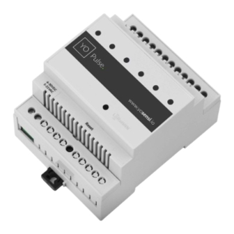
Product description Overview The YO Pulse is used for monitoring logical states, alarm detection or pulse counting. Based on the data collected by the device, it is possible to: monitor the states of devices and processes in automation. Collect the number of pulses from measuring devices, for example, from water meters. -
Page 5: Physical Interfaces
Physical interfaces LEDs YO Pulse communicates its current behavior to the user by RGBW LED placed on the top of the device shown on figure one. It also has orange diodes which count pulses sent to the network. DIODE STATUES INTERPRETATION... -
Page 6: Specifications
YO Pulse User guide v1.2 page 6/26 Specifications Physical Figure 3 Dimensions of the device. PHYSICAL SPECIFICATION Dimensions Height: 90 mm Width: 71,2 (4 pole) mm Depth: 58 mm Colour Light grey Mounting method 35 mm DIN rail Vertical (can be screwed to the wall) -
Page 7: Operating Conditions
YO Pulse User guide v1.2 page 7/26 Operating conditions OPERATING CONDITIONS Temperature 0° to 70°C Humidity 0 to 90% Placement Indoor use Power supply 6 - 30 V DC 5 - 21 V AC Power consumption Typical: 20 mA DC (12 V DC) - Page 8 YO Pulse User guide v1.2 page 8/26 Figure 4 Periodic counter on first channel exemplary chart. Figure 5 Example of a normally open contact monitoring chart. Figure 6 Example of a normally closed contact monitoring chart. www.yosensi.io...
-
Page 9: Installation
YO Pulse User guide v1.2 page 9/26 Installation Package contents Device. Warranty card. Safety precautions SAFETY PRECAUTIONS SYMBOL DESCRIPTION Device is marked with a symbol saying that electrical and electronic products may not be mixed with unsorted household waste. Remember that batteries used to power the device must be treated at a specialized treatment facility. -
Page 10: Installation Guide
YO Pulse User guide v1.2 page 10/26 Installation guide 1. Mount the device on a 35 mm DIN rail. Figure 7 Device mounting instructions. 2. Connect the inputs to the individual channels of the device according to the polarity shown on the enclosure label. - Page 11 YO Pulse User guide v1.2 page 11/26 3. Screw the power supply wires to the device regardless of polarity (6 - 30 V DC, 5 - 21 V AC). Figure 9 Input cable passing through the cable gland instructions. 4. After connecting the wires diodes should behave as it is described on physical interfaces of the LEDs.
-
Page 12: Operation
3. Server – in most cases, a cloud-based service where data is processed, stored, analysed, and presented in user-friendly ways (via a user interface); Yosensi default and recommended tools are Yosensi Management Platform (for IoT structure management) and Grafana (for data presentation). -
Page 13: Device Configuration
(generic): configuration data required to connect to the LoRaWAN, ble (generic): bluetooth settings, device (dynamic): individual configuration for a specific device (the structure of this section is different for each device). Sample configuration file for the YO Pulse device. "info": { "devmodel": "LNDI", "fwver": "3.6.1", "loraradio": "SX1261",... - Page 14 YO Pulse User guide v1.2 page 14/26 GENERICS PARAMETERS SECTION NAME DESCRIPTION POSSIBLE DEFAULT READ/ VALUES VALUE WRITE devmodel Device name LNDI fwver Firmware version 3.6.1 loraradio Radio chipset model SX1261 info lorawanver LoRaWAN stack version 1.0.2 loraregion LoRaWAN region...
-
Page 15: Parameters Description
YO Pulse User guide v1.2 page 15/26 DEVICE PARAMETERS NAME DESCRIPTION POSSIBLE DEFAULT READ/ VALUES VALUE WRITE measinterval Measuring and sending interval 120–999999 LoRa [s] debouncetime Delay for pulse counting preventing 1-1000 from contact vibration of the device [ms] chxfunc... - Page 16 YO Pulse User guide v1.2 page 16/26 UPLINK SUBBAND REGION DESCRIPTION POSSIBLE DEFAULT READ/ VALUES VALUE WRITE EU868 Sub-band 1; 867.1 - 868.5 MHz; channels 0-7 Sub-band 1; 902.3 - 903.7 MHz; channels 0-7 Sub-band 2; 903.9 - 905.3 MHz; channels 8-15 Sub-band 3;...
-
Page 17: Configuration Node With Yosensi Management Platform
YO Pulse User guide v1.2 page 17/26 Configuration node with Yosensi Management Platform Connect to the device as follows: 1. Log in at app.yosensi.io 2. You’ll see the dashboard organization view. Go to the Application section in the sidebar. 3. Select the application and locate and select the device by looking for the DEV EUI on the device label that matches the NODE ID in the list. -
Page 18: Configuration Node With Yosensi Mobile App
Configuration node with Yosensi mobile app Connect to the device using Yosensi app as follows: 1. Login to your account using the Yosensi mobile app. 2. Go to the device section (the middle button) and choose the device or your organization with the devices attached to it. -
Page 19: Connecting Node With Network
IoT systems management (like the root directory in operating systems). It can be created only by Yosensi staff, and all clients using Yosensi Management Platform have one created for them by default. In case of any questions, you can find us at support@yosensi.io. - Page 20 Select a model that is compatible with your device — this choice affects the number of charts and data source (YO Pulse). You can also set the node’s ‘Location’ , if locations have been pre-defined. If you haven’t defined a suitable location, leave this field set at <None>.
- Page 21 YO Pulse User guide v1.2 page 21/26 Figure 17 Node creation form. www.yosensi.io...
- Page 22 5. New nodes must be added in OTAA mode. Nodes can be switched to ABP mode after activation in the Yosensi Management Platform by changing the Node configuration. Click on the link in the ‘Node Name’ column. Go to the ‘KEYS’ tab and switch ‘LoRa Type’ from OTAA to ABP and fill in the blank spaces, then press update.
-
Page 23: Adding Node Via Bluetooth
Extended documentation of the protocol can be found in the Payload description on our website. An example payload produced by YO Pulse is presented below with divisions for each measurement and marked with decoded values, whose interpretation is described in the Payload description. - Page 24 YO Pulse User guide v1.2 page 24/26 Third measurement (CH3 - NC state) 0x04 0x00 0x11 0x13 0x00 0x00 type = 1, addr_len = 1, state = 1* val = 0 md [s] = 0 prec = 0 meas_len = 2...
-
Page 25: Compliance Statements
YO Pulse User guide v1.2 page 25/26 Compliance statements www.yosensi.io... - Page 26 YO Pulse User guide v1.2 page 26/26 www.yosensi.io...
Need help?
Do you have a question about the YO Pulse and is the answer not in the manual?
Questions and answers