Table of Contents
Advertisement
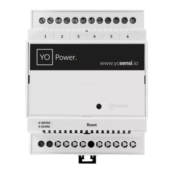
Quick Links
Advertisement
Table of Contents

Related Manuals for YOSensi YO Power


Summary of Contents for YOSensi YO Power
- Page 1 YO Power User guide v3.0...
-
Page 2: Release Notes
YO Power User guide v1.0 page 2/27 Release notes Date Version Changes Initial release. 11.06.2021 Change of power supply from 100~240 V AC, 50/60 Hz to 6 07.12.2021 - 30 V DC, 5 - 21 V AC Added specifications of the device, Installation instruction, 06.09.2022... -
Page 3: Table Of Contents
Temperature and relative humidity Battery condition Installation Package contents Safety precautions Installation guide Operation IoT system components Device configuration Configurable parameters Parameters description Configuration via CLI Connecting node with network Yosensi Management Platform configuration Payload description Compliance statements Revision history REV 3.0 www.yosensi.io... -
Page 4: Product Description
Product description Overview The YO Power measures AC flowing through devices connected to the electricity grid. With one YO Power it is possible to measure the current simultaneously (e.g., in two three-phase, six single-phase, one three-phase and three single-phase devices, etc.). It is possible to install current clamps without knowing the direction through which the current flows. -
Page 5: Physical Interfaces
BLE MAC: bluetooth physical address Figure 2 Device sticker. Physical interfaces LEDs YO Power communicates its current behavior to the user by RGBW LED placed on the top of the device shown on figure one. DIODE STATUES INTERPRETATION BEHAVIOUR COLOUR DEVICE STATUS Single flash... -
Page 6: Specifications
YO Power User guide v1.0 page 6/27 Specifications Physical Figure 3 Dimensions of the device. PHYSICAL SPECIFICATION Dimensions Height: 90 mm Width: 71,2 (4 pole) mm Depth: 58 mm Colour Light grey Mounting method 35 mm DIN rail Vertical (can be screwed to the wall) -
Page 7: Operating Conditions
YO Power User guide v1.0 page 7/27 Operating conditions OPERATING CONDITIONS Temperature 0° to 70°C Humidity 0 to 90% Placement Indoor use Power supply 6 - 30 V DC 5 - 21 V AC Power consumption Typical: 12 mA DC (12 V DC) - Page 8 Current flow on second channel of the device exemplary chart. Power consumption Power consumption measured by YO Power and attached to it CT clamps is a value calculated for each hour for 230 V and current flowing on each channel. It helps monitor customers how much power is consumed by the devices every hour and check anomalies in the electric network.
-
Page 9: Installation
YO Power User guide v1.0 page 9/27 Installation Package contents Device. Warranty card. Safety precautions SAFETY PRECAUTIONS SYMBOL DESCRIPTION Device is marked with a symbol saying that electrical and electronic products may not be mixed with unsorted household waste. Remember that batteries used to power the device must be treated at a specialized treatment facility. -
Page 10: Installation Guide
YO Power User guide v1.0 page 10/27 Installation guide 1. Mount the device on a 35 mm DIN rail. Figure 6 Device mounting instructions. REV 3.0 www.yosensi.io... - Page 11 YO Power User guide v1.0 page 11/27 2. Connect the inputs to the individual channels of the device according to the polarity shown on the enclosure label. Figure 7 Connect the inputs to the individual channels of the device. REV 3.0...
- Page 12 YO Power User guide v1.0 page 12/27 3. Fasten the current clamps around the wires in which the current is to be measured (a clamp should be placed around one wire). Figure 8 Instruction on how to fasten the current clamps around the wires.
- Page 13 YO Power User guide v1.0 page 13/27 4. Screw the power supply wires to the device regardless of polarity (6 - 30 V DC, 5 - 21 V AC). Figure 9 Instruction on how to connect the power to the device.
- Page 14 YO Power User guide v1.0 page 14/27 Figure 10 Final look of the device. REV 3.0 www.yosensi.io...
-
Page 15: Operation
3. Server – in most cases, a cloud-based service where data is processed, stored, analysed, and presented in user-friendly ways (via a user interface); Yosensi default and recommended tools are Yosensi Management Platform (for IoT structure management) and Grafana (for data presentation). -
Page 16: Device Configuration
(generic): configuration data required to connect to the LoRaWAN, ble (generic): bluetooth settings, device (dynamic): individual configuration for a specific device (the structure of this section is different for each device). Sample configuration file for the YO Power device. "info": { "devmodel": "LNPW", "fwver": "3.2.0", "loraradio": "SX1261",... - Page 17 YO Power User guide v1.0 page 17/27 GENERICS PARAMETERS SECTION NAME DESCRIPTION POSSIBLE DEFAULT READ/ VALUES VALUE WRITE devmodel Device name LNPW fwver Firmware version 3.2.0 loraradio Radio chipset model SX1261 info lorawanver LoRaWAN stack version 1.0.2 loraregion LoRaWAN region...
-
Page 18: Parameters Description
Measurement threshold for each 2A, 10 A, 50A, channel 100 A chxcttype Number of channel, for x equal from 50mA-100 A, 50mA-100 1 to 6, between the YO Power 40mA-160 A, device and type of current 50mA-200A, transformer sensor clamp 50mA-400A, 50mA-600A, 50mA-800A Parameters description nwktype: used for setting the device in public or private network type. - Page 19 YO Power User guide v1.0 page 19/27 UPLINK SUBBAND REGION DESCRIPTION POSSIBLE DEFAULT READ/ VALUES VALUE WRITE EU868 Sub-band 1; 867.1 - 868.5 MHz; channels 0-7 Sub-band 1; 902.3 - 903.7 MHz; channels 0-7 Sub-band 2; 903.9 - 905.3 MHz; channels 8-15 Sub-band 3;...
-
Page 20: Configuration Via Cli
Connecting node with network According to the LoRaWAN architecture, to transmit data on the network there should be a configured Gateway and Network Server.. We’ll go through an example in our recommended Yosensi Management Platform software. REV 3.0 www.yosensi.io... -
Page 21: Yosensi Management Platform Configuration
(YO Power). You can also set the node’s ‘Location’ , if locations have been pre-defined. If you haven’t defined a suitable location, leave this field set at <None>. - Page 22 5. Every new node must be added in OTAA mode. You must then switch its type to ABP after activation in Yosensi Management Platform by changing the Node configuration. Click on the link in the ‘Node Name’ column. Go to the ‘KEYS’ tab and switch ‘Lora Type’ from OTAA to ABP, and fill in the ‘Device Address’...
-
Page 23: Payload Description
Payload description. An exemplary payload produced by YO Power is presented below with division into each measurement marked together with decoded values whose interpretation is described in the Payload description document. Example of YO Power payload with description:... - Page 24 YO Power User guide v1.0 page 24/27 *The payload starts building from the 2nd channel of the device. Data for the first channel is taken from the second measurement and at that point data from the second channel of the second measurement is cut.
-
Page 25: Compliance Statements
YO Power User guide v1.0 page 25/27 Compliance statements REV 3.0 www.yosensi.io... - Page 26 YO Power User guide v1.0 page 26/27 REV 3.0 www.yosensi.io...
-
Page 27: Revision History
YO Power User guide v1.0 page 27/27 Revision history Date Version Changes Initial release. 11.06.2021 Change of power supply from 100~240 V AC, 50/60 Hz to 6 07.12.2021 - 30 V DC, 5 - 21 V AC Added specifications of the device, Installation instruction, 06.09.2022...
Need help?
Do you have a question about the YO Power and is the answer not in the manual?
Questions and answers