YOSensi YO Airflow Pro User Manual
Hide thumbs
Also See for YO Airflow Pro:
- User manual (27 pages) ,
- User manual (27 pages) ,
- User manual (27 pages)
Table of Contents
Advertisement
Quick Links
Advertisement
Table of Contents

Related Manuals for YOSensi YO Airflow Pro


Summary of Contents for YOSensi YO Airflow Pro
- Page 1 YO Airflow Pro User guide v1.0...
-
Page 2: Release Notes
YO Airflow Pro User guide v1.0 page 2/26 Release notes Released Version Key changes 05.09.2022 Initial release. REV 1.0 www.yosensi.io... -
Page 3: Table Of Contents
Temperature and relative humidity Battery condition Installation Package contents Safety precautions Installation guide Operation IoT system components Device configuration Configurable parameters Parameters description Configuration via CLI Connecting node with network Yosensi Management Platform configuration Payload description Compliance statements Revision history REV 1.0 www.yosensi.io... -
Page 4: Product Description
LoRaWAN region and 3 parameters important in case of device identification and configuration: DEV EUI: unique device identifier required to connect via OTAA connection type to LoRaWAN. DEV ADDR: address required to connect via ABP connection type to LoRaWAN. BLE MAC: bluetooth physical address. REV 1.0 www.yosensi.io... -
Page 5: Physical Interfaces
BLE communication: connection to the device via BLE (configuration). Rapid flashing Blue LoRaWAN communication: connecting to LoRaWAN network. Buttons YO Airflow Pro is equipped with one reset button inside the device on the PCB board next to the RGBW LED diode. REV 1.0 www.yosensi.io... -
Page 6: Specifications
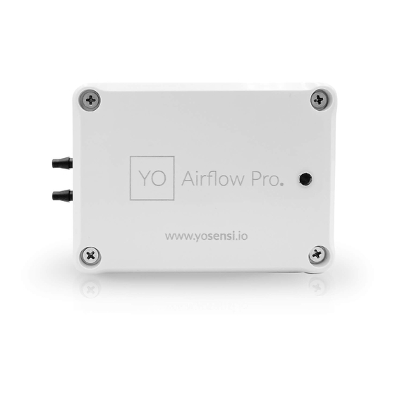
Dimensions of the device. PHYSICAL SPECIFICATION Dimensions Height: 42 mm Width: 88 mm Depth: 64 mm Colour Light grey Mounting method Horizontal Vertical (can be screwed to the wall) Enclosure material Level of protection IP67 Weight 248 g REV 1.0 www.yosensi.io... -
Page 7: Operating Conditions
Differential pressure is measured by two separate compartments. Measurements inform users about maintaining air flow and quality of airflow. Sudden drops in the chart from adopted standards can inform about worn air filters. Figure 4 Differential pressure monitoring chart. REV 1.0 www.yosensi.io... -
Page 8: Temperature And Relative Humidity
Temperature and relative humidity are measured by sensors placed inside the device enclosure. These measurements can be used to monitor if the device is working in recommended conditions. Figure 5 Internal temperature monitoring chart. Figure 6 Internal humidity monitoring chart. REV 1.0 www.yosensi.io... -
Page 9: Battery Condition
Battery voltage is used to monitor its condition – to spot anomalies (like sudden drop) or its current condition based on voltage drop over time in comparison to initial voltage rating. Figure 7 Battery voltage exemplary chart. REV 1.0 www.yosensi.io... -
Page 10: Installation
Clean the device only with damp cloth. Device is intended for outdoor and indoor use. Make sure that device is not exposed for long term UV rays and in an environment in the immediate vicinity of water which may flood the device REV 1.0 www.yosensi.io... -
Page 11: Installation Guide
1. Unscrew the device: remove 4 screws from the enclosure. Figure 8 Device opening instructions. 2. Place three LR6 batteries in the device according to the polarity indicated on the battery holder. Figure 9 Battery placement instructions. REV 1.0 www.yosensi.io... - Page 12 First tubes must be cut off on the edge of the sensor with high or low pressure, then cut off the rest of the silicon tube located along the black sensor. Then take off the rest of the silicon tube gently without breaking the sensor. REV 1.0 www.yosensi.io...
- Page 13 ● The sensor measuring the higher pressure must be placed where the higher pressure occurs ● The sensor measuring the lower pressure must be placed where the pressure is lower Figure 12 Connecting silicone tubing with brackets instructions. REV 1.0 www.yosensi.io...
-
Page 14: Operation
3. Server – in most cases, a cloud-based service where data is processed, stored, analysed, and presented in user-friendly ways (via a user interface); Yosensi default and recommended tools are Yosensi Management Platform (for IoT structure management) and Grafana (for data presentation). -
Page 15: Device Configuration
"blemacaddr": "0123456789ab" "lorawan": { "subband": 1, "nwktype": "public", "acttype": "otaa", "otaa": { "deveui": "0123456789abcdef", "appeui": "fedcba9876543210", "appkey": "000102030405060708090a0b0c0d0e0f", "trials": 3 "abp": { "devaddr": "01234567", "nwkskey": "0123456789abcdef0123456789abcdef", "appskey": "000102030405060708090a0b0c0d0e0f" "ble": { "power": 0, "interval": 1600 "device": { "measinterval": 3600 REV 1.0 www.yosensi.io... - Page 16 LoRa radio chipset used defines the LoRaWAN region: SX1261 - EU868; SX1262 - AU915, US915, AS923 Uplink subband list for specific LoRaWAN regions - UPLINK SUBBAND Table. Calculation formula: MS_INPUT = INTERVAL_MS × 1.6. Change currently not supported. REV 1.0 www.yosensi.io...
-
Page 17: Parameters Description
BLE receiver around the device. subband: used for setting the communication frequency sub-band in LoRaWAN. measinterval: interval of sending each LoRa payload. REV 1.0 www.yosensi.io... - Page 18 Sub-band 6; 923.2 - 924.6MHz; channels 40-47 Sub-band 7; 924.8 - 926.2 MHz; channels 48-55 Sub-band 8; 926.4 - 927.8 MHz; channels 56-63 Sub-band 1; 922.0 -923.2 MHz; channels 0-8 AS923 supported Sub-band 2; 923.2 - 924.5 MHz; channels 9-17 REV 1.0 www.yosensi.io...
-
Page 19: Configuration Via Cli
Connecting node with network According to the LoRaWAN architecture, to transmit data on the network there should be a configured Gateway and Network Server.. We’ll go through an example in our recommended Yosensi Management Platform software. REV 1.0 www.yosensi.io... -
Page 20: Yosensi Management Platform Configuration
IoT systems management (like the root directory in operating systems). It can be created only by Yosensi staff, and all clients using Yosensi Management Platform have it created for them by default (in case of any problems you can find us on support@yosensi.io). - Page 21 5. Every new node must be added in OTAA mode. You must then switch its type to ABP after activation in Yosensi Management Platform by changing the Node configuration. Click on the link in the ‘Node Name’ column. Go to the ‘KEYS’ tab and switch ‘Lora Type’ from OTAA to ABP, and fill in the ‘Device Address’...
-
Page 22: Payload Description
An exemplary payload produced by YO Airflow Pro is presented below with division into each measurement marked together with decoded values whose interpretation is described in the Payload description document. Example of YO Airflow Pro payload with description: 02:00:00:00:08:00:01:11:ce:0d:00:01:00:f0:10:00:00:42:41:00:05:fe:f5:00:60:00:bd:15:00:01:08: ab:0d:00:11:25:00:f7 REV 1.0 www.yosensi.io... - Page 23 = 2 (221,9 [Pa]) Sixth measurement (gas temperature) 0x0D 0x00 0x11 0x37 0x00 0xF7 type = 3, addr_len =1, val = 247 md [s] = 0 addr = 25 prec = 1 meas_len = 2 (24,7 [°C]) REV 1.0 www.yosensi.io...
-
Page 24: Compliance Statements
YO Airflow Pro User guide v1.0 page 24/26 Compliance statements REV 1.0 www.yosensi.io... - Page 25 YO Airflow Pro User guide v1.0 page 25/26 REV 1.0 www.yosensi.io...
-
Page 26: Revision History
YO Airflow Pro User guide v1.0 page 26/26 Revision history Date Version Changes 05.09.2022 Initial release. REV 1.0 www.yosensi.io...
Need help?
Do you have a question about the YO Airflow Pro and is the answer not in the manual?
Questions and answers