GEDA 300 Z Assembly And Operating Manual
Rack and pinion hoist for loads
Hide thumbs
Also See for 300 Z:
- Operating manual (104 pages) ,
- Operating manual (101 pages) ,
- Assembly and operating manual (128 pages)

Subscribe to Our Youtube Channel
Related Manuals for GEDA 300 Z


Summary of Contents for GEDA 300 Z
- Page 1 Assembly and operating manual Rack and pinion hoist For loads Original assembly and operating manual...
- Page 3 Rack and pinion hoist Assembly and operating manual 3 / 92 BL131 GB Edition 08.2015...
- Page 4 Rack and pinion hoist Assembly and operating manual 4 / 92 BL131 GB Edition 08.2015...
-
Page 5: Table Of Contents
Rack and pinion hoist Table of Contents: Section Page General information ........................... 7 Information about the operating manual ..................7 Information about the machine ....................7 Name and address of the manufacturer ..................8 Notes about the author and industrial property rights ..............8 Instructions for the operating company .................. -
Page 6: Section Page
Rack and pinion hoist Section Page Installation ............................47 Safety during installation ......................47 Assembling the base unit ......................48 Extending mast sections and anchoring to the building ............50 6.3.1 Trailing cable guide ....................... 55 6.3.2 Limit switch approach bar ..................... 56 Safeguarding loading and unloading points ................ -
Page 7: General Information
Information about the machine Type of machine GEDA 300 Z Serial number: 14770 (400 V) 16430 (230 V) Year of manufacture: see type plate of the machine Documentation version:... -
Page 8: Name And Address Of The Manufacturer
Violations are an offence and incur an obligation to pay compensation. All rights to exercise industrial property rights are reserved by GEDA. Assembly and operating manual 8 / 92... -
Page 9: Instructions For The Operating Company
Any replacement and wear parts that are used must correspond to the technical requirements stipulated by GEDA. This is ensured with original replacement parts. Only use qualified and/or instructed personnel for the activities described in this manual. -
Page 10: Proper Use
Rack and pinion hoist Proper use The GEDA 300 Z rack and pinion hoist is a construction hoist that is temporarily erected and • which is intended exclusively for putting up scaffolding and as additional equipment (landing level safety gates) for transporting items and materials during construction work. -
Page 11: Requirements Of Assembly Personnel
• The 300 Z is not designed for permanent installation. • The 300 Z may not be constructed to be free-standing (without anchors). • Persons who have not been instructed in the machine and who are not acquainted with the operating manual, and children, may not operate the hoist. -
Page 12: General Safety Information
Rack and pinion hoist General safety information The machine has been designed and built according to the latest standards of technology and recognised safety-related rules. Nevertheless, hazards for personnel or third parties and/or damage to machinery and other tangible assets can occur during use, e.g. if the machine: Is operated by untrained or uninstructed personnel, −... -
Page 13: Safety Instructions For Operating Personnel
Rack and pinion hoist Safety instructions for operating personnel The operating manual must be within reach at all times at the place where the machine is used. The machine may only be used in a technically fault-free condition, as well as in accordance with the intended use, in a safety conscious manner aware of the hazards, and while observing the operating manual! In particular rectify faults immediately that could impair safety! In addition to this, the machine may only be operated when all safety... -
Page 14: Safety Instructions For Transport
Rack and pinion hoist Safety instructions for transport Report transport damage and/or missing parts immediately to the supplier. Wear a hard hat, safety shoes and safety gloves during transport work! Never step under suspended loads! Only use appropriate, standardised and tested lifting gear, forklifts, cranes) and sling gear (round slings, lifting straps, sling ropes, chains) for transport at the assembly site. -
Page 15: Safety Instructions For Operation
Rack and pinion hoist Safety instructions for operation Use the machine only in a technically fault-free condition, in a safety conscious manner and aware of the hazards, while also observing the operating manual. If work is interrupted, switch the machine off at the main switch and secure it with a padlock against being switched back on. -
Page 16: Safety Instructions For Servicing, Maintenance And Troubleshooting
Rack and pinion hoist Safety instructions for servicing, maintenance and troubleshooting Operating personnel must be informed about how to carry out special work and maintenance work before they start. Deadlines/intervals that are stipulated or stated in the operating manual for recurring tests/inspections must be adhered to. The area of maintenance must be generously cordoned off as required! In principle, before any service work on the machine... - Page 17 Rack and pinion hoist The machine, especially general connections and screw connections, must be cleaned of any oil, working materials, dirt/grime and maintenance products. Aggressive cleaning agents may not be used. During servicing and maintenance work, loosened screw connections must always be re-tightened with the necessary torques! Do not change, remove, bypass or bridge safety devices.
-
Page 18: Safety During Work On The Electrics
Rack and pinion hoist Safety during work on the electrics If there are faults on the electrical system of the machine, it must be shut down immediately using the main switch and secured with a lock or the mains plug must be removed! Work on the electrical equipment of the machine may only be carried out by professional electricians working in accordance with electrical engineering regulations! Only professional electricians may access the... -
Page 19: Checks
Rack and pinion hoist Checks Inspections prior to commissioning, recurring inspections and intermediate inspections must be carried out according to national regulations. During the checks, the condition, presence and function of all safety- related features of the machine are checked using appropriate procedures. -
Page 20: Checks Before Initial Commissioning
Recurring checks must be carried out in accordance with national regulations. GEDA recommends that you carry out a recurring check on an annual basis. In the event of increased demand (e.g. multiple shift operation), carry out checks at shorter intervals. -
Page 21: Dynamic Tests
Rack and pinion hoist Dynamic tests With empty platform/car • Drop test after each assembly. • Drop test in accordance with the maintenance schedule. • Drop test after replacing the safety gear With loaded platform/car • Drop test before initial commissioning (refer to Chapter 3.2) •... -
Page 22: Checks After Extreme Weather Conditions
Rack and pinion hoist Checks after extreme weather conditions Special check after temperatures of – 40 °C [-40 °F] NOTE: If it is unclear if the temperature was less than – 40 °C [-40 °F], follow procedures as if this temperature had been reached when starting up the machine again. -
Page 23: Technical Description
Rack and pinion hoist Technical description Description of function The GEDA 300 Z is a vertically installed rack and pinion hoist which is used exclusively for transporting scaffold parts, objects and construction material. • The base unit can be extended with 0.7 m, 1 m and 2.0 m long mast sections up to a max. - Page 24 Rack and pinion hoist Use as a scaffold hoist A specific use of the hoist is for scaffold assembly, the scaffold and hoist are installed alternately (hoist and scaffolding are in assembly state). • A mobile ground control is used for operation or only the assembly control in the platform is used during assembly.
-
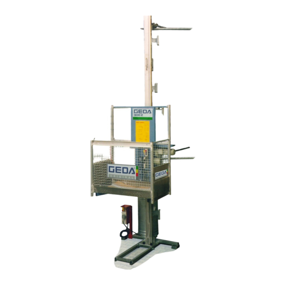
Page 25: Machine Equipment
Rack and pinion hoist Machine equipment 1 = Foot section with base mast 7 = Mast sections 2 m (1 m, 0.66 m) 2 = Limit switch approach bar for the 8 = Limit switch approach bar for landing lowermost loading point level stop 3 = Cable bin 9 = Anchoring tubes... - Page 26 Rack and pinion hoist 1 = Drive motor 2 = Safety brake 3 = Switch cabinet with main switch 4 = Switch cabinet on sliding carriage Switch cabinet with main switch Assembly • Place the bracket with switch cabinet onto the foot section and screw down.
- Page 27 Rack and pinion hoist Manual control/ground control The cable for the plug-in control is 5 m long. 1 = EMERGENCY STOP button 2 = Selector switch MANUAL (I) - AUTOMATIC (II) 3 = UP button 4 = DOWN button 5 = Hanging bracket Assembly control 1 = EMERGENCY STOP button 2 = Overload control lamp...
- Page 28 Rack and pinion hoist Sliding carriage switch cabinet 1 = Key switch - To the left Outside control (manual control/ground control and electric modules on the landing levels) is active. - To the right assembly control is active. 2 = Earthing contact socket outlet 230 V/16 Amp. 3 = Plug-in device for the trailing cable Overrun protection The overrun protection switches off upward travel during assembly...
- Page 29 Rack and pinion hoist Limit switch approach bar for UP A limit switch approach bar for UP (1) must be installed as top stop point. The limit switch approach bar for UP (1) limits upward travel. Limit switch approach bar for landing level stop A limit switch approach bar for a landing level stop (1) can be placed at each stop position so...
-
Page 30: Equipment As Accessories
Rack and pinion hoist Equipment as accessories 4.3.1 Standard push-on frame for the load platform 1 = Standard push-on frame for safe transport of scaffold components Tools required: 2 ring or open-jaw spanners - width across flats 13/17 1 screwdriver Assembly ... -
Page 31: Special Push-On Frames
Rack and pinion hoist 4.3.2 Special push-on frames 1 + 2 = Special push-on frames for safe transport of scaffold components Pipe bracket Tools required: 2 ring or open-jaw spanners - width across flats 13/17 1 screwdriver Assembly for load platform with ramp Assemble the lateral push-on frame (2) as described in section... - Page 32 Rack and pinion hoist Insert the special push-on frame part (1) into the front corner strut (3) and screw down using the two hex screws (4) M 8 x 55, washers and nuts supplied (boreholes are provided). Screw down the special push-on frame part (1+2) using two cups (5) and two hex screws M 8 x 50,...
-
Page 33: Spindle
Rack and pinion hoist 4.3.3 Spindle Spindle for easy alignment of the base unit. Three spindles can be installed on the foot section. 4.3.4 Manoeuvrable bogie The manoeuvrable bogie makes it easier to manoeuvre on the construction site or storage area if there is no crane or forklift available. Assembling the manoeuvrable bogie ... -
Page 34: Single Axle Trailer
This single axle trailer can be fitted with a trailer coupling ring for cars or alternatively with a trailer coupling ring for lorries. The transport of the 300 Z with the trailer is described in a special operating instructions 4.3.6... -
Page 35: Technical Data
Rack and pinion hoist Technical data Load capacity: 300 kg The machine is equipped with an overload device that switches off the travel movement in both directions when the load capacity is exceeded; a red warning lamp lights up in the platform. Overload is not measured during travel! Anchoring distance: max. -
Page 36: Data For 230 V Drive
Rack and pinion hoist 4.4.1 Data for 230 V drive Voltage supply: 230 V/50 Hz Drive output: 1.8 kW Rated (drive) current: 10.5 A Drive traction power: 4500 N Duty cycle (DC) S3 (60 %) Lifting speed: 20 m/min Max. assembly height: 50 m Weights: - Base unit... -
Page 37: Extension To Base Unit
Rack and pinion hoist 4.4.4 Extension to base unit Length of one mast element: 0.7 m / 1 m / 2 m Bolt tightening force: 90 Nm Aluminium mast 0.7 m 8.5 kg Aluminium mast 1 m 14 kg Aluminium mast 2 m 25 kg Mast brackets 4 kg... -
Page 38: Anchoring And Spatial Requirement
Rack and pinion hoist Anchoring and spatial requirement Assembly and operating manual 38 / 92 BL131 GB Edition 08.2015... - Page 39 Rack and pinion hoist Assembly in front of a wall Assembly in front of scaffolding Assembly and operating manual 39 / 92 BL131 GB Edition 08.2015...
- Page 40 Rack and pinion hoist Legend Distance between wall fixtures See the anchoring forces below Distance from the centre of the circular See the anchoring forces below mast tube to the wall Width of the load platform 1.48 m Depth of the load platform 0.83 m Height of the base unit (with assembly 2.15 m...
- Page 41 Rack and pinion hoist Anchoring forces The anchoring forces can be found in the following tables, depending on the respective location (see wind map), assembly height and assembly situation. Details are given of the peak forces occurring for the assembly geometry shown; they do not include any safety factors. The appropriate anchoring forces must be requested if the assembly geometry shown is changed.
- Page 42 Rack and pinion hoist Assembly in front of a wall A = approx. 0.82 m, B = approx. 0.68 m B x 1.2 Anchoring forces [kN] with Anchoring forces [kN] ≥ maximum mast projection without mast projection Top anchor Other anchor Top anchor Other anchor point...
- Page 43 Rack and pinion hoist Assembly in front of a scaffolding A = approx. 2.5 m, B = approx. 1.38 m (with a scaffold field depth of approx. 0.7 m) Anchoring forces [kN] with Anchoring forces [kN] A ≥ B x 1.7 maximum mast projection without projecting mast Top anchor...
-
Page 44: Requirements For The Site Of Installation
Rack and pinion hoist Requirements for the site of installation 4.6.1 Foundation • The foundation must be horizontal and have sufficient load bearing capacity. The foundation must be compacted according to the floor load − [kN/m²] (see assembly height). • Depending on the assembly height, wooden planks or steel sheeting, for example, can be used as load distributing base supports. -
Page 45: Mains Connection
A building site main cabinet (according to IEC 60439-4:2004) with fuse protection of the supply point with min. fusing of 16A slow-to-blow is required on site. 300 Z with 230 V drive Supply point: 230 V / 50 Hz −... -
Page 46: Transport
Rack and pinion hoist Transport Have the hoist transported by experienced and qualified persons. Inspection on receiving the hoist • Check the shipment for transport damage and for completeness according to the purchase order. • Immediately notify the freight carrier (haulage company) and dealer of any transport damage. -
Page 47: Installation
• Protection to prevent persons from falling must be provided at loading heights above 2.0 m (use only original GEDA landing level safety gates). • Observe the load capacity of the hoist. -
Page 48: Assembling The Base Unit
Rack and pinion hoist Assembling the base unit • Set the base unit at the support points (spindle support plates and especially on the foot section support beneath the mast) onto load distributing, even base supports and align (see section 4.5). Observe load bearing capacity of the foundation! ... - Page 49 Rack and pinion hoist Replacing the cable bin Unplug the trailing cable on the switch cabinet of the sliding carriage. Dismantle the eye bolt (1) and screw (2) with the track roller. Take the trailing cable holder (3) out of the mount and place it in the cable bin.
-
Page 50: Extending Mast Sections And Anchoring To The Building
Rack and pinion hoist Extending mast sections and anchoring to the building If the equipment is erected in front of scaffolding it must be anchored to the building. It can also be anchored directly to the scaffolding if the scaffolding has been designed for the additional load (see anchoring forces). - Page 51 Rack and pinion hoist Clamp bracing tube (3) into the mobile coupling on the mast bracket (2) and guide it to the wall. Choose the widest possible distance between both anchoring points on the wall (at least 0.80 m). For anchoring forces, see the anchoring forces table.
- Page 52 Rack and pinion hoist Inspection before mast assembly Raise the empty load platform (manual control) and check if the proximity switch shuts the unit down at the end of the mast. − the last (platform side) lowered mast fixing device actuates the −...
- Page 53 Rack and pinion hoist Push key into the key switch on the sliding carriage switch cabinet and turn to the right (assembly position). The ramp and fall protection must be closed and the assembly guard plate must be up and secured. Before the platform ascends, ensure that the base unit is standing securely.
- Page 54 Rack and pinion hoist Place the first mast element (12) onto the base mast (11) by hand. Lift and tighten three eye bolts (11A). Tightening torque − approx 90 Nm. The adjustable connecting plate (11B) of the base mast must be pushed up and secured with the eye bolt.
-
Page 55: Trailing Cable Guide
Rack and pinion hoist Maintain vertical distances for: - Mast anchors max. 4 m. - Trailing cable guides approx. 8/4 m. Check trailing cable length! Assemble the hoist until the desired height is reached (max. 50 m with 230 V drive or 100 m with a 400 V drive). ... -
Page 56: Limit Switch Approach Bar
Rack and pinion hoist 6.3.2 Limit switch approach bar An emergency limit switch bar (1) must be installed as top stop point before the drive pinion leaves the gear rack. Adhere to a minimum distance to the top of the mast end of 1.0 m. Assembly The limit switch tag must point to the motor side. -
Page 57: Safeguarding Loading And Unloading Points
Rack and pinion hoist Safeguarding loading and unloading points Protection to prevent persons from falling is to be provided at all loading and unloading points at heights above 2 m. The "ECO" landing level safety gate, together with the loading ramp on the load platform, provides safe transfer to the building or scaffold. -
Page 58: Limit Switch Approach Bar For Landing Level Stop
Rack and pinion hoist Assembly and operation of the electric module is described in the assembly instructions for the landing level safety gate. Limit switch approach bar for landing level stop A limit switch approach bar for a landing level stop can be placed at each stop position so that the platform stops at the same level as the landing level safety gate. -
Page 59: Inspections After Assembly And Before Commissioning
(See section 9.7.) • Key for assembly control is removed. Check the GEDA 300 Z according to national regulations after assembly and before initial commissioning, as well as after each assembly at a new construction site or any other new site. -
Page 60: Special Features When Using As A Scaffold Hoist
Rack and pinion hoist Special features when using as a scaffold hoist The overrun protection (proximity switch) shuts down the ascend function during assembly. It can be minimally adjusted in height to match the scaffold level with the load platform floor. Since the scaffold heights and mast elements always jump by 2.0 m, the proximity switch (1) does not need to be adjusted any more for further assembly work. -
Page 61: Operation
Rack and pinion hoist Operation The GEDA 300 Z may only be operated by a qualified person appointed by the operating company. This person must be acquainted with the operating manual, have sufficient experience and be informed about the risks involved in working with the hoisting equipment. -
Page 62: Safety Inspection Before Starting Work
The load platform must emit a warning tone in both travel directions when it is near to the ground (approx. 2 m). When near to the ground (approx. 2 m), the GEDA 300 Z must not be able to be operated from the landing gate. Assembly and operating manual 62 / 92 BL131 GB Edition 08.2015... -
Page 63: Using The Platform Access Point, Turning Lever And Landing Level Safety Gate
Rack and pinion hoist Using the platform access point, turning lever and landing level safety gate 7.3.1 Ramp Open Unlatch the ramp (1) at the interlock hook (2) and lower the ramp. Close Raise the ramp (1) and press against the platform until the interlock hook (2) clicks into place twice. -
Page 64: Eco" Landing Level Safety Gate
Rack and pinion hoist 7.3.3 "ECO" landing level safety gate Turn the load platform towards the landing level safety gate. Open the landing level safety gate Take the key (1) out of the attachment (2) on the load platform. -
Page 65: Operating The Hoist
Rack and pinion hoist Operating the hoist The platform must be turned towards the sliding carriage and latched into place. The ramp must be closed and the assembly guard plate must be up and secured. Turn the main switch to "I". ... - Page 66 Rack and pinion hoist Automatic travel to a landing level Selector switch (2) to position "II" Ascent The load platform travels within the lower 2.0 m from the ground (safety height) only as long as the UP button (3) is pressed. After passing this safety height, the UP button (3) must be released and the platform will travel automatically to the next...
-
Page 67: Emergency Shutdown
Rack and pinion hoist Emergency shutdown In situations that present a risk to operating personnel or the hoist, the platform can be shutdown by pressing the EMERGENCY STOP button. There is an EMERGENCY STOP button on the manual control. ... -
Page 68: Dismantling (Disassembly)
Rack and pinion hoist Dismantling (disassembly) The rack and pinion hoist must be dismantled according to the assembly and operating manual under supervision by a qualified person, specifically appointed by the operating company! Assembly personnel, see section 1.6.1 The same rules and safety instructions as described in section 6 apply for dismantling. -
Page 69: Servicing And Cleaning
Maintenance work may only be carried out by qualified persons. Report any changes or malfunctions immediately to the company management or his/her authorised representative. If necessary, shut down and secure the GEDA 300 Z immediately. Before cleaning and maintenance work, first lower the platform and remove the mains plug. -
Page 70: Monthly Servicing
Rack and pinion hoist Check the overload control light on the assembly control by manually pressing the overload limit switch (1). Monthly servicing • Check that the mast connection bolts, limit switch approach bars and mast anchors/bolts are secured to the mast and the building, tighten if necessary. -
Page 71: Quarterly Servicing
The grease reservoir must be refilled before it empties. Filling quantity: 1.2 l Recommended lubricant: Multi-purpose grease/cartridge for grease gun, GEDA Item No. − 16744. Attach manual lever grease gun to the filling nipple (1) -
Page 72: Six Monthly Maintenance
= 13 mm). Servicing every 6 years GEDA safety gear must be replaced with new GEDA safety gear (safety gear exchange units) after 6 years at the latest. The obligation to replace safety gear applies to both material hoists and personnel hoists. -
Page 73: Inspecting The Overspeed Safety Brake In The Context Of The Recurring Inspection
Rack and pinion hoist Inspecting the overspeed safety brake in the context of the recurring inspection (See also section Fehler! Verweisquelle konnte nicht gefunden werden.) The safety brake test may only be carried out by a qualified person, specifically appointed by the operating company who, based on his or her training, knowledge and practical experience, can evaluate the risks and assess the safe condition of the overspeed safety brake. -
Page 74: Faults - Diagnosis - Repairs
Rack and pinion hoist Faults - diagnosis - repairs Faults may only be rectified by qualified persons! Before troubleshooting, lower the platform (if possible) and unload! Shut off and secure the main switch before working on the rack and pinion hoist's electrical system. Remove the mains plug for safety's sake. - Page 75 Rack and pinion hoist *If the green control light lit is not lit, check the following points (only on machines with 400 V drive): Is there a phase failure? − Is the phase sequence incorrect? − If the phase sequence is incorrect, correct it on the phase inverter (1) (power supply plug) by turning the two plug pins 180°...
-
Page 76: Potential Faults During Operation
Rack and pinion hoist 10.1 Potential faults during operation 10.1.1 Power failure or defective motor If this happens the load platform must be lowered to the ground by releasing the motor brake. Take the brake release lever (1) out of the mount (2) and screw into the brake release thread (3). -
Page 77: Load Platform Has Been Driven Too High
Rack and pinion hoist 10.1.2 Load platform has been driven too high The platform-facing eye bolt on the top mast section actuates the rocker switch of the emergency limit switch before the drive pinion leaves the gear rack. Cause The emergency limit switch is operated, if the limit switch approach bar for UP is not installed and the proximity −... -
Page 78: Overload Warning Device Has Triggered
Rack and pinion hoist The lower range of the gear rack is fitted with a rack and pinion segment (2) with predetermined breaking point. This rack and pinion segment (2) prevents the drive unit being damaged in the event of any impact against the foot section. -
Page 79: Overspeed Safety Brake Has Been Triggered
10.2 Overspeed safety brake has been triggered The GEDA 300 Z is equipped with an overspeed safety brake which stops the platform in the event of it overspeeding. Further travel is not possible once the overspeed safety brake has been triggered. -
Page 80: Repairs
The rating plate is located on the sliding carriage of the base unit. Spare parts must meet the technical specifications of the manufacturer! Only use original spare parts from GEDA. For service or repair work, please contact our customer service department: For the sales and customer service address, see section 1.3... -
Page 81: Appendix A Summary Of Instruction Notices
Rack and pinion hoist Appendix A Summary of instruction notices Item No. 05242 Item No. 11935 only with a 400 V drive (all switch cabinets) (switch cabinet with main switch) Item No. 33697 Item No. 14657 (sliding carriage switch (sliding carriage switch cabinet) cabinet) Item No. - Page 82 Rack and pinion hoist Item No.16688 Item No. 16521 (assembly guard plate) (manual control) Item No. 14565 (assembly guard plate) Assembly and operating manual 82 / 92 BL131 GB Edition 08.2015...
-
Page 83: Appendix B Entries For Recurring Inspections
Rack and pinion hoist Appendix B Entries for recurring inspections Documentation for regular checks in accordance with the maintenance schedule unplanned check after specific events Name: Serial number: Year of manufacture: Works number: The machine was checked on______________. As a result none ... - Page 84 Rack and pinion hoist Documentation for regular checks in accordance with the maintenance schedule unplanned check after specific events Name: Serial number: Year of manufacture: Works number: The machine was checked on______________. As a result none the following ...
- Page 85 Rack and pinion hoist Documentation for regular checks in accordance with the maintenance schedule unplanned check after specific events Name: Serial number: Year of manufacture: Works number: The machine was checked on______________. As a result none the following ...
- Page 86 Rack and pinion hoist Documentation for regular checks in accordance with the maintenance schedule unplanned check after specific events Name: Serial number: Year of manufacture: Works number: The machine was checked on______________. As a result none the following ...
- Page 87 Rack and pinion hoist Documentation for regular checks in accordance with the maintenance schedule unplanned check after specific events Name: Serial number: Year of manufacture: Works number: The machine was checked on______________. As a result none the following ...
- Page 88 Rack and pinion hoist Documentation for regular checks in accordance with the maintenance schedule unplanned check after specific events Name: Serial number: Year of manufacture: Works number: The machine was checked on______________. As a result none the following ...
- Page 89 Rack and pinion hoist Space for notices Notice entered Name: / Date Position Assembly and operating manual 89 / 92 BL131 GB Edition 08.2015...
- Page 90 Rack and pinion hoist Space for notices Notice entered Name: / Date Position Assembly and operating manual 90 / 92 BL131 GB Edition 08.2015...
- Page 92 GEDA -Dechentreiter GmbH & Co. KG Mertinger Straße 60 86663 Asbach-Bäumenheim Tel.: +49 (0)9 06 / 98 09-0 Fax: +49 (0)9 06 / 98 09-50 E-Mail: info@geda.de Web: www.geda.de BL131 GB Edition 08/2015...
Need help?
Do you have a question about the 300 Z and is the answer not in the manual?
Questions and answers