Table of Contents
Advertisement
Quick Links
Advertisement
Table of Contents

Related Manuals for IBA ibaLink-VME


Summary of Contents for IBA ibaLink-VME
- Page 1 VMEbus Interface Board Manual Issue 1.8...
- Page 2 Required corrections are contained in the following regulations or can be down- loaded on the Internet. The current version is available for download on our web site http://www.iba-ag.com. Protection note Windows® is a label and registered trademark of the Microsoft Corporation. Other prod- uct and company names mentioned in this manual can be labels or registered trade- marks of the corresponding owners.
-
Page 3: Table Of Contents
8.1.2 Switch Settings on Front Panel of ibaLink-VME ........... 26 Settings for ALSPA C80 HPC (Logidyn D2) ..........27 8.2.1 Engineering notes for ibaLink-VME with ALSPA C80 HPC (Logidyn D2) ..27 8.2.2 Card Settings ....................27 8.2.3 Use of the ibaLink-VME in SM128 compatibility mode ......... 28 8.2.4... - Page 4 Card Settings ....................35 8.3.3 Use of the ibaLink-VME in SM128 compatibility mode ......... 36 8.3.4 Use of the ibaLink-VME in 32Mbit P2P mode or 32Mbit Flex mode ..... 37 Settings for GE 90/70 .................. 38 8.4.1 Card settings ....................38 8.4.2...
-
Page 5: About This Manual
About this manual This compact manual provides the information for installation and handling of the VME interface board ibaLink-VME. For further information concerning the system integration and software configuration please refer to the corresponding engineering manuals and / or software documentation of our software products used in conjunction with this device. -
Page 6: Used Symbols
Manual ibaLink-VME Used symbols If safety instructions or other notes are used in this manual, they mean: The non-observance of this safety information may result in an imminent risk of death or severe injury: • By an electric shock! Due to the improper handling of software products which are coupled to input and •... -
Page 7: Introduction
Block coherent mode Data exchange between 2 systems in Peer-to-Peer mode (P2P) The ibaLink-VME can be used in both VME32 and VME64 systems (6U height). 5 V power supply is required (from VMEbus). VME specification according to ANSI VITA 1-1994: ... - Page 8 Using 32Mbit Flex protocol ibaLink-VME is compatible to all 32Mbit Flex-enabled iba- devices. ibaLink-VME can be connected within a ring to these devices. But the card cannot com- municate with the other devices, only with the Flex master (at the moment only ibaPDA) ...
-
Page 9: Scope Of Delivery
Manual Scope of delivery After unpacking check the completeness and intactness of the delivery. The scope of delivery includes: Device ibaLink-VME Manual Safety instructions Designated use The device is an electrical equipment. It may be used only in the following applications: ... -
Page 10: System Requirements
ibaFOB-2i-D optional with extension module ibaFOB-4o-D ibaFOB-4i-D optional with extension module ibaFOB-4o-D ibaFOB-io-ExpressCard Coupling to an automation system iba system connection as partner of the computer coupling iba I/O device Software Coupling to a PC system ... -
Page 11: Installation / Deinstallation
Avoid direct contact with the connectors. Preferably hold the card only by the front panel. Each ibaLink-VME occupies a single slot in the VME rack. Installing the card Before installation / deinstallation of the card switch off the power supply of the VMEbus rack. -
Page 12: Removing The Card
Special note for installing the ibaLink-VME card in a GE 90/70 system rack The GE90/70 system rack has no openings for the guide pins of the ibaLink-VME card. If this fact has not been considered when ordering the card, the guide pins have to be removed before installing the card. -
Page 13: Device Description
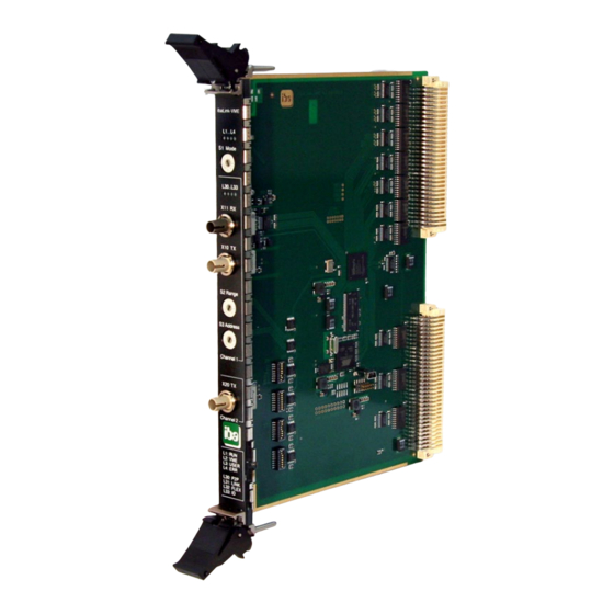
(5) Channel 1 FO transmitter X10 TX (6) Rotary switch S2 Range (7) Rotary switch S3 Address (8) Channel 2 FO transmitter X20 TX Figure 1 View on front panel of ibaLink-VME 7.1.1 Fiber optic connections Channel 1: X11 RX (4) and X10 TX (5) Channel 1 communicates bidirectionally with compatible devices over the RX and TX interface ports. -
Page 14: Rotary Switches
7.1.2 Rotary switches S1 „Mode“ (2) This switch sets the mode of operation for the ibaLink-VME interface card. The modes of operation vary in the used ibaNet protocol, the transmission rate, size and format of the telegrams. See chapter 7.2 “Operation modes”. -
Page 15: Status Leds
LED can be controlled by ibaPDA I/O Manager in 32Mbit Flex (green) mode This could help identifying an ibaLink-VME card in a rack Table 2: Channel LEDs No LEDs are assigned for channel 2, since this channel is only an output channel in 3Mbit mode or a copy of channel 1. -
Page 16: Operation Modes
Manual ibaLink-VME Operation modes The S1 “Mode” switch specifies the operation mode, especially the used ibaNet protocol, the telegram size and the timebase. Depending on the operation mode several devices can be cascaded or coupled in peer- to-peer mode. The X20 TX output at channel 2 can be used as independent output chan- nel, or it can be used for diagnostics when the data of channel 1 is mirrored to this output. -
Page 17: Ibanet 3Mbit With Diagnostics (Mode 1)
Manual Overlapping of Address/Range Settings When the data ranges of several daisy-chained devices overlap each other, the subse- quent card in a daisy-chain will overwrite the values of the previous card. However, all values of the previous card are available in the DPR* of the subsequent card. -
Page 18: Ibanet 3Mbit P2P (Mode 8)
Manual ibaLink-VME 7.2.3 ibaNet 3Mbit P2P (mode 8) In peer-to-peer-(P2P)-mode 2 cards can be coupled to each other, exchanging data (64 analog and 64 digital signals) periodically in 1 ms (computer coupling). In this oper- ation mode the two VMEbus memory ranges are transmitted from one card to the other. -
Page 19: Ibanet 32Mbit P2P (Mode 4)
Manual 7.2.5 ibaNet 32Mbit P2P (mode 4) The “fast” peer-to-peer mode is also used to connect two cards, but more signals can be transmitted at a higher data rate. Channel 2: the data of channel 1 is mirrored to channel 2 and can be used for diagnostics (e.g. -
Page 20: 32Mbit Flex (Mode F)
65 bytes at 25 µs, the maximum amount of data is 4060 bytes at 1.4 ms). The ibaLink-VME card can be connected with up to 15 devices in a ring topology with 32Mbit Flex. 32Mbit Flex requires a FO card of the ibaFOB-D type for communication. -
Page 21: Dip Switches On Board
Manual DIP Switches on Board The DIP switches are located in the lower part of the board. They are used for setting interrupts, data formats and the board’s base memory address in the VME address space. VMEbus- connectors (J1, J2) -
Page 22: Function Of Dip Switches
Manual ibaLink-VME 7.3.1 Function of DIP Switches DP1 – Data format no function RSVD1 no function no function RSVD2 no function no function RSVD3 no function Coherent Mode enabled COHERENT Non-coherent Channel 1 Big Endian CH1-BIG-ENDIAN Channel 1 Little Endian... - Page 23 Manual Coherent mode (DP1.5) The coherent mode can be activated here. Coherent mode means, that data of a processing cycle are transferred in one FO telegram. To enable coherent data transmission proceed as follows: After writing to the transmit buffer, the sender has to release the data transfer by setting the 0xE8.7 bit in the DPR.
-
Page 24: Setting The Vmebus Start Address
Manual ibaLink-VME 7.3.2 Setting the VMEbus Start Address The lower two DIP switches are used for setting the VME memory address of the card in hex-code. The assignment of DIP switch bits and address is shown in the picture below with start address 0x77900000 as an example. -
Page 25: Settings For Host Systems
CONVERTEAM GmbH, ALSTOM Power Conversion, AEG-Cegelec or AEG. In order to use the ibaLink-VME board in this system it is required to use a modified version with a single connector to the 16 bit VME backplane. In the lower part of the system's backplane in the rack there is the PMB bus. -
Page 26: Card Settings
Manual ibaLink-VME A sample program (*.O32 object file) is available on request from iba AG, Germany, which uses the addresses mentioned above in this example. Furthermore, we can pro- vide a LogiCAD documentation of a sample application. The object must be linked to the Logidyn application program, i. -
Page 27: Settings For Alspa C80 Hpc (Logidyn D2)
Four VMEbus addresses are reserved by GE Energy for the operation of ibaLink-VME cards. Hence up to 4 ibaLink-VME cards can be used in one HPC rack. The memory ranges are 512 kByte wide, though only 256 kByte are currently used, with reference for future extensions. -
Page 28: Use Of The Ibalink-Vme In Sm128 Compatibility Mode
Use of the ibaLink-VME in SM128 compatibility mode Transferring values to the VME memory range In order to write data into the memory range of the ibaLink-VME card, a subroutine – the so called parameter block “IBA_SM128V” – must be used in the application program. - Page 29 Manual Settings for Hardware (WINRDTM): 8.2.3.1 Switch Settings on Front Panel of ibaLink-VME 3Mbit protocol: switch S1 = 0, S2 = 8, S3 = 1. Issue 1.8...
-
Page 30: Use Of The Ibalink-Vme In 32Mbit P2P Mode
P2P module in mode D. Transferring values to the VME memory range In order to write data into the memory range of the ibaLink-VME card, a subroutine – the so called parameter block “VMIC_IBA” – must be used in the application program. - Page 31 Manual Administration in HPC (LogiCAD) A VMIC_IBA block and a time management (synchronization) must be programmed for operation of one or more ibaLink-VME cards. Link Statement (LogiCAD) The application program must include a link statement to the library LIB386\VMIC_IBA.LIB...
- Page 32 Manual ibaLink-VME Hardware Configuration in HPC The ibaLink-VME card has to be entered as OEM device in the hardware configuration. Settings for Hardware (WINRDTM): 8.2.4.1 Switch Settings on Front Panel of ibaLink-VME 32Mbit P2P: switch S1 = 4, S2 = D, S3 = x...
- Page 33 Manual 8.2.4.2 Specific settings in ibaPDA See chapter Configuration in 32Mbit P2P mode for setting up a P2P module in ibaPDA. In ibaPDA V6.38.0 or higher, adding a new module with S2 range switch set to D will automatically set the number of analog signals to 974 and the number of digital signals to 1024.
- Page 34 Manual ibaLink-VME 8.2.4.3 Example of the use of the VMIC_IBA block in LogiCAD Issue 1.8...
-
Page 35: Settings For Hpci
GE Energy. It is the successor of the ALSPA C80 HPC (Logidyn D2) sys- tem. The standard version of the ibaLink-VME interface card can be used in an HPCi rack with operating system VxWorks and programming system ALSPA P80i. -
Page 36: Use Of The Ibalink-Vme In Sm128 Compatibility Mode
Manual ibaLink-VME Figure 8 DIP switch, settings for up to four ibaLink-VME cards in ALSPA C80 HPCi 8.3.3 Use of the ibaLink-VME in SM128 compatibility mode 8.3.3.1 Writing the data into the VME memory range In order to write data into the VME memory range the corresponding VMEWRT function blocks must be included in the application program. -
Page 37: Use Of The Ibalink-Vme In 32Mbit P2P Mode Or 32Mbit Flex Mode
Manual 8.3.4 Use of the ibaLink-VME in 32Mbit P2P mode or 32Mbit Flex mode 8.3.4.1 Writing the data into the VME memory range In order to write data into the VME memory range the corresponding VMEWRT function blocks must be included in the application program. -
Page 38: Settings For Ge 90/70
Byte order: Big Endian Data format: REAL Figure 9 DIP switch, settings for GE 90/70 (one, respectively first ibaLink-VME card) 8.4.2 Switch Settings on Front Panel of ibaLink-VME 3Mbit protocol: switch S1 = 0, S2 = 8, S3 = 1 32Mbit P2P: switch S1 = 4, S2 depending on data amount, S3 = x 32Mbit Flex: S1 = F, S2 = x, S3 = 1…F (device address). -
Page 39: Settings For Simatic Tdc
When using an ibaLink-VME board in a Siemens Simatic TDC automation system a Si- matic TDC module must not be inserted to the right of the ibaLink-VME board in a TDC rack! Due to the dynamic address allocation, a required initializing signal to the TDC module is not transmitted via the slot where an ibaLink-VME board is inserted. - Page 40 One or more blocks are to be used per inserted card. Block example: Important note These functional modules are not provided by iba. Please contact the local Siemens branch office or Siemens AG in Erlangen, Germany. Issue 1.8...
-
Page 41: Card Settings
Manual 8.5.2 Card settings The yellow marks show the switch position. Figure 10: DIP switch, settings for SIMATIC TDC (one, respectively first ibaLink-VME card) Settings: Mode: A32 Byte order: Little Endian Data format: REAL (according to the data format, which is supported by the functional module). -
Page 42: System Topologies
Each link transmits 64 analog and 64 digital signals, i.e. a total of 128 signals. For outputs from ibaPDA to ibaLink-VME, a FO output link and a FO connection to the RX port of ibaLink-VME is necessary. In ibaPDA I/O manager add a module “FOB alarm”... -
Page 43: Configuration In 32Mbit P2P Mode
When using 32Mbit P2P mode, connect a simplex FO cable from TX1 or TX2 to the ibaFOB-D card. In ibaPDA I/O manager add an „ibaLink-VME (P2P)“ module at the con- nected link and specify the connection mode in the field “S2 range switch”, which corre- sponds to the S2 switch setting. - Page 44 Manual ibaLink-VME Advanced Mode If you enable the option „Advanced Mode“ you can make some additional settings. Figure 14 ibaLink-VME (P2P) module, advanced mode Advanced Swap digital signals Digital signals can be inverted (true/false) Read digital signals You can choose between 8 bit, 16 bit or 32 bit access to digital signals. Depending on this setting, the bit numbering in the table of the digital signals changes.
-
Page 45: Configuration In 32Mbit Flex Mode
1. Start the ibaPDA client and open the I/O manager 2. Choose the correct ibaFOB-D input card in the signal tree (on the left hand side) and mark the link ibaLink-VME is connected to. Right-click on the link and choose “Auto- detect”. - Page 46 Manual ibaLink-VME ibaLink-VME – General tab Figure 15: ibaLink-VME – General tab Basic settings Locked A locked module can only be changed by an authorized user. Enabled Here, you can activate data capturing for this module (True). Name ...
- Page 47 The changed settings become valid by clicking on <OK> or <Apply>. ibaLink-VME – Analog tab Figure 16: ibaLink-VME – Analog tab Please enter here the analog signals to be recorded sequentially. The columns in the signal list have got the following meaning: Name ...
- Page 48 Displays the actual value of the signal (only available when the measurement is already running with the specified configuration). ibaLink-VME – Digital tab Figure 17: ibaLink-VME – Digital tab Name, Active, Actual see „Analog“ tab. Address, Bit no.
- Page 49 Loading the update takes some minutes. When the update installation is finished, you will be asked to reset the ibaLink-VME module, i.e. the rack the module is plugged in. Reset to factory defaults The configuration settings will be deleted.
- Page 50 Manual ibaLink-VME The digital signals are listed in the digital tab and the analog signals are listed in the analog tab. For each signal you can specify an expression using the expression builder. Figure 20: Output signals Issue 1.8...
-
Page 51: Ibalogic Application
FO card, the following modes can be used. In order to use the outputs of the ibaLogic application the fiber-optic input link at channel 1 of the ibaLink-VME card must be connected to the output link of an ibaFOB-2io-D card in the ibaLogic-PC. -
Page 52: Ibalogic V4 Configuration
The 3Mbit modes and the 32Mbit P2P mode are supported. In I/O Configurator under the connected link, specify the mode which corresponds to the ibaLink-VME mode. When a bidirectional connection is used, the same mode must be selected for input and output. - Page 53 Manual Assigning the connection mode in ibaLogic under ibaPADU-S-IT: Use the input and output resources "FiberOptics_IO". Figure 23: FO link setting under ibaPADU-S-IT ibaLogic Signal ibaLink-VME Description link protocol type switch position External Integer S1 = 8, S2 = x DIP switch DP1.1/1.3 according...
-
Page 54: Cascade With 3Mbit Mode
The address switch position determines the slot to be occupied. After the last ibaLink-VME card all slots are filled with data. The FO input of the ibaFOB card receives 8 x 8 = 64 signals. - Page 55 #3 should point on 5. Flow of Data Considerations Be careful to note that the data is written to each ibaLink-VME local dual port RAM. Consider the example above, card #2 receives 16 signals from card #1, card #3 re- ceives 16 signals from card #1 and 16 signals from card #2.
-
Page 56: Cascade With 32Mbit Flex
Cascade with 32Mbit Flex Up to 15 ibaLink-VME cards or other iba devices, which support 32Mbit Flex mode, can be cascaded in a FO ring (only channel 1). Switch S3 (Address) specifies a unique device address 1…F, which corresponds to an address 1..15. -
Page 57: Process I/O Mode
Manual Process I/O Mode ibaLink-VME can serve as a process i/o bus extender for PLC systems. ibaPADU-8-O can be used as an output device, ibaPADU-8 devices as inputs. Up to 8 devices can be connected to channel 1 (each input and output), up to 8 output devices can be connected to channel 2. -
Page 58: The Vmebus Interface
DIP switch. Whether the link sends in integer or float format must be defined prior to installing the ibaLink-VME. Use the DIP switch to change this setting for each fiber optic link. Each fiber-optic link can be set independently. -
Page 59: Global Overview
Manual 10.2 Global overview The address space is compatible with the SM128. Reserved areas return zero on reads. Writing to reserved areas has no effect. Global overview of the 256K address space: Offset Range 0x0000-0x00FF Control/Status/Version Registers 0x0100-0x0FFF Reserved... -
Page 60: Control/Status/Version Registers
Manual ibaLink-VME 10.3 Control/Status/Version registers Offsets which are not mentioned are reserved (do not write to them). Except where men- tioned, registers are read-only. For SM128 compatible modes, the version registers contain SM128 identification strings in order to maximize compatibility with the real SM128 boards. -
Page 61: Sm128 Rx/Tx
Manual 10.4 SM128 RX/TX Remark: byte: format not influenced by the Endianess DIP switch Dword: format depending on the Endianess DIP switch Offset Format Meaning 0x1801 byte Fiber Optic Input Status & DIP Status Channel 1 Bit0: 0=link down... -
Page 62: Rx/Tx Buffers
Manual ibaLink-VME Coherent Mode When Coherent Mode is enabled, the output data is only sent to the fiber optic output after setting the TX1/TX2 Commit bit in the Control Register 0xE8. Committing the TX buffers should not happen faster than 10 µs! When Coherent Mode is enabled, the input data is only updated to the last received data after setting the RX1 Get bit in the Control Register 0xE8. -
Page 63: Technical Data
Technical Data 11.1 Main data Manufacturer iba AG, Germany Order no. ibaLink-VME: 14.132000 ibaLink-VME-16Bit: 14.132001 (on request) Communication channels Channel 1: In-/Output Channel 2: Output ibaNet protocols 3Mbit, 32Mbit, 32Mbit Flex Connector type 2 ST connectors for RX and TX The use of fiber optic cables of type 62.5 μm/125... -
Page 64: Dimension Sheet
Supplier's Declaration of Conformity 47 CFR § 2.1077 Compliance Information Unique Identifier: 14.132000 ibaLink-VME Responsible Party - U.S. Contact Information iba America, LLC 370 Winkler Drive, Suite C Alpharetta, Georgia 30004 (770) 886-2318-102 www.iba-america.com FCC Compliance Statement This device complies with Part 15 of the FCC Rules. Operation is subject to the following two conditions: (1) This device may not cause harmful interference, and (2) this device must ac- cept any interference received, including interference that may cause undesired operation. -
Page 65: Example For Fo Budget Calculation
Manual 11.3 Example for FO budget calculation As an example, an FO connection from an ibaFOB-io-Dexp card (FO transmitter) to an ibaBM-PN device (FO receiver) is used. Figure 1: Example: simple connection for FO budget calculation The example refers to a point-to-point connection with an FO cable of type 62.5/125 µm. - Page 66 Manual ibaLink-VME Equation for calculating the FO budget (A Budget ���� = |(���� − ���� ������������������������ ���� ���������������� ���� �������� ���� �������������������� = sensitivity of FO receiving interface Receiver = output power of FO transmitting interface Sender Equation for calculating the fiber optic cable length (l ����...
-
Page 67: Support And Contact
Mailing address iba AG Postbox 1828 D-90708 Fuerth Germany Delivery address iba AG Gebhardtstrasse 10 D-90762 Fuerth Germany Regional and Worldwide For contact data of your regional iba office or representative please refer to our web site www.iba-ag.com. Issue 1.8...
Need help?
Do you have a question about the ibaLink-VME and is the answer not in the manual?
Questions and answers