Table of Contents
Advertisement
Quick Links
Advertisement
Table of Contents

Related Manuals for IBA ibaFOB-4i-S


Summary of Contents for IBA ibaFOB-4i-S
- Page 1 Version 3.2 3.1 en...
- Page 2 iba AG 2009 all rights reserved. ibaFOB-4i-S / -io-S - Manual V 3.2 en / ibaFOB A2 / A8 We have checked that the contents of this manual match the hardware and software de- scribed here. However, deviations cannot be fully ruled out, so that we cannot assume any warranty should any deviations actually exist.
-
Page 3: Table Of Contents
8.3.1. LEDs ......................17 8.3.2. 7-Segment Display.................17 8.3.3. Fiber Optic Interface of ibaFOB-io-S............17 8.3.4. Fiber Optic Interfaces of ibaFOB-4i-S ............17 8.3.5. Fiber Optic Interfaces of ibaFOB-4o (optional) ........18 8.3.6. Fiber Optic Interfaces of ibaFOB-OF-Link (optional)......18 8.3.7. Synchronisation Output Module ibaFOB-Sync-Out (optional)....19 8.3.8. -
Page 4: This Manual
A reference to additional documentation or more in-depth literature. iba training courses Hint for training courses by iba concerning related products or subjects Copyright notice Windows is a registered trademark of Microsoft Corporation. Other product or company names mentioned in this manual may be brand names or regis- tered trademarks of the corresponding owner. -
Page 5: Introduction
The boards ibaFOB-io-PCI, ibaFOB-io-S, ibaFOB-4i-PCI, ibaFOB-4i-S, ibaFOB-4o and ibaFOB-OF-Link are fiber optic communication cards which are used to connect a stan- dard PC to the iba peripheral devices such as ibaPADUs, ibaNet750-BM devices and ibaLink signal modules (SM). As far as the following text does not refer to a particular card, the boards are referred to as ibaFOB boards. - Page 6 Manual ibaFOB-4i-S / -io-S The ibaFOB-4i-S or ibaFOB-io-S devices represent the new generation of iba's fiber optic PC boards. These boards replace the ibaFOB x/4, ibaFOB x/4-F and ibaFOB 2/2 IO boards which were based on the PC ISA bus definition. The new boards are 100% com- patible on the fiber optical bus side while in the PC the interface and dual port ram layout differ between the old and new boards.
-
Page 7: Scope Of Delivery
/ -io-S Manual Page 7 Scope of Delivery The following components are included with the delivery. ibaFOB-4i-S or ibaFOB-io- PCI device (6-wire flat ribbon cable with four jacks for iba card synchronization) Manual Safety Information Please consider the following safety advises:... -
Page 8: Installation / Uninstallation
Page 8 Manual ibaFOB-4i-S / -io-S Installation / Uninstallation Preparation The card fits in every compatible PCI slot. C A U T I O N ! Use a ground line or discharge any electrostatic charge from yourself before touching the card. -
Page 9: Installing The Card
/ -io-S Manual Page 9 Installing the Card Switch off the PC, disconnect it from power supply and open it, so that you can see the PCI slots. Unpack the card carefully. Use a ground line or discharge any electrostatic charge from yourself before touching the card. -
Page 10: System Requirements
At least one free PCI slot 128 MB RAM or better Please see http://www.iba-ag.com for further details on a properly outfitted workstation. Software Microsoft Windows NT 4.0 (Service Pack 5 or higher), 2000, XP or 2003 Server ... -
Page 11: Driver Installation
Page 11 Driver installation Windows XP The ibaFOB-4i-S and ibaFOB-io-S cards comply with the Plug & Play standard of Win- dows. After the card has been plugged in for the first time and after Windows has finished its startup after booting the Found New Hardware Wizard pops up for introduction to the in- stallation of the drivers. - Page 12 The system is looking for driver software and installs it automatically. Finally click on <Fin- ish>. If you like to check if the card was properly installed open the Windows „Device Manager“ and look for the card under the iba devices node. iba AG 2012...
-
Page 13: System Integration
I/O system for 256 analog and 256 digital in- and outputs. To do this connect the ibaFOB-4o to the ibaFOB-4i-S (with the 10 pole connector). The ibaFOB-4o as well as the ibaFOB-4i-S hold the additional connector (6-pole) to wire the ibaFOB-OF-Link card which monitors the in and outputs without additional time delay. - Page 14 Page 14 Manual ibaFOB-4i-S / -io-S If the PC power supply is switched OFF, all “monitored signals” are off because the monitoring involves an optical – electrical –optical conversion - which cannot work without the PC´s power supply. ...
-
Page 15: Device Description
One bi-directional (ibaFOB-io-S) or four unidirectional (ibaFOB-4i-S) independent fiber optic channels Expansion connector for ibaFOB-4o to get four bi-directional channels on an iba- FOB-4i-S. Each optical link has its own processor with up to 5 Mbit/s ... -
Page 16: Views, Displays And Connectors
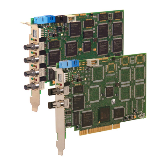
Page 16 Manual ibaFOB-4i-S / -io-S Views, Displays and Connectors 8.2.1. ibaFOB-io-S ibaFOB-OF-Link-connector Sync-i / Sync-o-connector Sync-IRQ-connector 7-Segment display LEDs Receiver (grey) Transmitter (white) 8.2.2. ibaFOB-4i-S ibaFOB-OF-Link- connector ibaFOB-4o- connector Sync-i / Sync-o- connector Sync-IRQ- connector 7-Segment display LEDs 4 receivers (grey) -
Page 17: Front Side Elements
8.3.4. Fiber Optic Interfaces of ibaFOB-4i-S The ibaFOB-4i-S provides four optical receivers (grey ST jacks). Channel 1 is located nearest to the 7-segment display. If the card was configured for external synchronization, e. g. for operation with an ibaBM-SLM, the first (upper) input channel needs to be connected with the external device for proper function (otherwise the whole PC process will be stopped). -
Page 18: Fiber Optic Interfaces Of Ibafob-4O (Optional)
The ibaFOB-4o provides four optical transmitters (white ST jacks). Channel #1 is the up- per channel. Beside the fiber optic ports, this module provides fur- ther connections to… - ibaFOB-4i-S (compatible to all predecessors) - ibaFOB-OF-Link Two different builds are available: a) with short front plate (picture) ibaRackline PCs have special slots in the housing for this kind of build. -
Page 19: Synchronisation Output Module Ibafob-Sync-Out (Optional)
PCs may be synchronized. The blue jacks on the flat ribbon cable should be plugged into the light blue connectors on the iba PCI- cards in the master PC. One card among these must be configured as interrupt master. -
Page 20: Configuration And Engineering
The entire configuration is to be done in the I/O-manager of ibaPDA-V6. The board is managed as data interface of type FOBF-PCI. The same interface type is used for ibaFOB-4i-S and ibaFOB-io-S. The system automati- cally detects which type(s) of card(s) are installed in the PC and displays them in the sig- nal tree 9.1.1. -
Page 21: Module And Signal Configuration
/ -io-S Manual Page 21 If you open the "link"-branches you can see the connected devices (= modules). Each link is subdivided in eight groups of eight channels each (64 in total per link) which corre- sponds to the smallest information package in the ibaPADU-8 philosophy. - Page 22 Page 22 Manual ibaFOB-4i-S / -io-S Under the tabs Analog and Digital you can enter and configure the signals. In the signal tables you can give a name to the signals assign physical units and limit val- ues (Max, Min) or set the signals active or passive. The column Actual shows already in- coming values when an active device is physically connected.
-
Page 23: Diagnosis
The main branch General in the tree view, tab Interrupt Info, shows the interrupt counter. The counter iba-Interrupts must have 1000 increments per second! If not, the interrupt master is missing. In this case check the card settings. In the dialog box of the link level (see 9.1.1), tab Info, you can see if the communication between ibaFOB card and ibaPADU device is working by checking the baud rate value. -
Page 24: Synchronization Of Several Boards
Manual ibaFOB-4i-S / -io-S Synchronization of Several Boards Shut down the computer, remove the power connection and plug in the other iba PCI cards. Connect the snyc-wire between the devices. This is now necessary because the PCI bus does not support any synchronization signal on the bus which is available at all slots si- multaneously. -
Page 25: Technical Data
/ -io-S Manual Page 25 Technical Data Order No.: ibaFOB-4i-S 11.115200 Order No.: ibaFOB-io-S 11.115300 Order No.: ibaFOB-4o 11.116000 Order No.: ibaFOB-OF-Link 11.113100 Mechanical: short PCI card ° ° Operating temperature: C to 50 C (32 °F…122 °F) °... -
Page 26: Support
90762 Fuerth Germany Phone: +49 911 97282-0 Fax: +49 911 97282-33 Email: iba@iba-ag.com Contact: Mr. Harald Opel Regional and Worldwide For contact data of your regional iba office or representative please refer to our web site www.iba-ag.com. iba AG 2012...
Need help?
Do you have a question about the ibaFOB-4i-S and is the answer not in the manual?
Questions and answers