Table of Contents
Advertisement
Quick Links
Advertisement
Table of Contents

Related Manuals for IBA ibaW-750


Summary of Contents for IBA ibaW-750
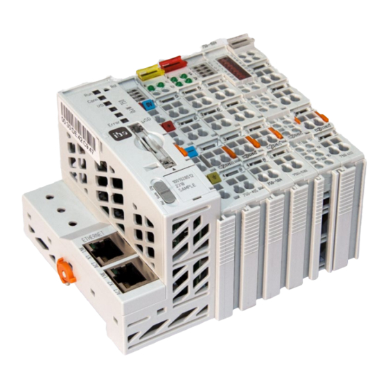
- Page 1 Central Unit for WAGO I/O System 750 Manual Issue 1.1...
- Page 2 Required corrections are contained in the following regulations or can be down- loaded on the Internet. The current version is available for download on our web site http://www.iba-ag.com. Windows is a label and registered trademark of the Microsoft Corporation. Other prod- ®...
-
Page 3: Table Of Contents
Manual Table of contents About this manual ................... 5 Target group ....................5 Notations ....................... 5 Used symbols....................6 Introduction ..................... 7 Scope of delivery..................... 9 Safety instructions ..................10 Designated use ................... 10 Special advices ................... 10 System requirements ..................11 Hardware .................... - Page 4 Device settings .................... 24 9.2.3 Owner of the device settings ............... 26 9.2.4 Add ibaW-750 ..................... 27 Module configuration ................... 31 9.3.1 ibaW-750 - Hardware .................. 31 9.3.2 ibaW-750 - Outputs ..................38 9.3.3 Diagnostics ....................39 Terminal types ....................43 10.1 Supported terminals ..................
-
Page 5: About This Manual
Manual About this manual This manual describes the construction, the use and the operation of the ibaW-750 de- vice. Target group This manual addresses in particular the qualified professionals who are familiar with han- dling electrical and electronic modules as well as communication and measurement tech- nology. -
Page 6: Used Symbols
Manual ibaW-750 Used symbols If safety instructions or other notes are used in this manual, they mean: The non-observance of this safety information may result in an imminent risk of death or severe injury: By an electric shock! Due to the improper handling of software products which are coupled... -
Page 7: Introduction
Ethernet. The WAGO I/O system of the 750 series is an ideal supplement to the iba system. Digital and analog I/O modules can be integrated into the system, as well as incremental en- coders, SSI inputs, RTDs, thermocouples and measuring bridges. - Page 8 While all iba devices normally deliver exactly 1 ms synchronized simultaneous snapshots of the process, this cannot be guaranteed when using the WAGO 750 I/O system. This is mainly due to the structure of the local serial I/O bus (K-bus). Further on, the cycle time depends on the number of channels connected to a station.
-
Page 9: Scope Of Delivery
Manual Scope of delivery After unpacking check the completeness and intactness of the delivery. The scope of delivery includes: ibaW-750 device ibaW-750 manual Issue 1.1... -
Page 10: Safety Instructions
The device is an electrical equipment. The device is only allowed for use in the follow- ing applications: Measurement data acquisition and analysis Applications of iba software products (ibaPDA etc.) The device is only to be applied as shown in the chapter Technical Data. Special advices The length of the supply line from the voltage source to the device must not exceed 30 m. -
Page 11: System Requirements
Standard Ethernet interface Standard Ethernet patch cable Optional: at least one free PCI/PCIe slot On our homepage http://www.iba-ag.com you will find several PC systems suita- ble for desktop or industry use. Ethernet network specification: Standard Ethernet topologies with router, switches, etc. -
Page 12: Mounting And Dismounting
Manual ibaW-750 Mounting and dismounting Important note Make sure the 24 V power supply is turned off when adding or removing modules. Mounting Press the device slightly against the DIN-rail. When you hear the click the device is securely mounted. -
Page 13: Device Description
Manual Device description Properties 24 V DC direct current supply (±10%), to supply the device and the K-bus. The power supply is able to supply I/O modules with a max of 1.7 A. If more current is needed, additional power supply modules must be integrated within the K-bus. -
Page 14: Device View
Manual ibaW-750 Device view Connectors Ethernet interfaces Operating element reset button Indicating element power supply Indicating element operating status Connectors local bus Connectors system power supply Connector memory card Connectors power jumper contacts Operating element configuration switch 10 Connector service interface... -
Page 15: Operating Elements
Manual Operating elements 7.4.1 Reset button The reset button can be used to reset the device to factory settings, see chapter 8.2. 7.4.2 Configuration switch The configuration switch is used to configure IP settings in addition to the reset:... - Page 16 Figure 2: System power supply If desired, you can order 24 V DIN rail or power supply units from iba. The 24 V voltage is internally converted to a 5 V operating voltage (galvanically con- nected). The voltage does not only supply the device, it also supplies connected modules via the local bus.
-
Page 17: Memory Card Slot
Manual Figure 3: Field power supply If desired, you can order 24V DIN rail or power supply units from iba. For power supply at field level please refer to chapter 7.5.5 7.5.4 Memory card slot Slot for microSD memory card for service purposes only. -
Page 18: System Integration
Figure 4: Data acquisition with ibaPDA ibaW-750 is connected to the ibaPDA computer via a standard Ethernet network. It is not relevant which of the two Ethernet interfaces is used. The device works with the ibaNet- E protocol for the transmission of configuration and measurement data. -
Page 19: Reset To Factory Settings
Figure 6: Connection via integrated switch ibaPDA automatically detects the ibaW-750 device and the connected modules if ibaW- 750 and the ibaPDA computer are in the same network (LAN). The sampling rate can be freely adjusted from 1 Hz to 1 kHz. The maximum amount of data that can be transmitted depends on the selected sampling rate. -
Page 20: Ibapda Integration
Figure 7: Open I/O Manager ibaNet-E interface The ibaW-750 device is connected via a standard Ethernet network card built into the ibaPDA computer and the ibaPDA interface ibaNet-E. Standard Ethernet infrastructure components can be used in this connection. Figure 8: ibaNet-E interface in the I/O Manager Issue 1.1... -
Page 21: Connections Tab
Interface extension, additional 2 connec- tions Note If you want to communicate bidirectionally with ibaW-750, e.g. to write control data and output signals in addition to data acquisition, you need a total of 2 connections, one for each direction. If only data is to be acquired in ibaPDA, only 1 connection is used by the license and the other one is available for the data acquisition of another ibaW-750. -
Page 22: Discovery Tab
<Search>. Device configuration If ibaW-750 is not yet configured for the network or this configuration is not known, a search can be started in the I/O Manager of ibaPDA. Please note that this search can only be successful if the device is located in the same LAN as the ibaPDA computer or has also been preconfigured for this LAN. -
Page 23: Search
Figure 11: ibaNet-E, Discovery tab In the field Network interfaces select the network card(s) via which you can reach the ibaW-750 device and start the search by clicking on <Search>: Figure 12: Found devices in the Discovery tab Found devices are listed in the table and cannot be changed in this display. -
Page 24: Device Settings
Edit device settings Owner If the device ibaW-750 has been configured before, the last owner is shown here, other- wise the field is empty (after delivery or resetting to factory settings). The owner corresponds to the computer name on which ibaPDA is installed and by which this device was most recently configured. - Page 25 If the settings are applied with <OK>, the following message appears and the input win- dow is closed. Figure 15: Message after having applied the settings The configured ibaW-750 device is displayed in the Discovery tab. Figure 16: Found devices Issue 1.1...
-
Page 26: Owner Of The Device Settings
9.2.3 Owner of the device settings If the device settings are opened again after the configuration in chapter 9.2.2, an owner is displayed, because the ibaW-750 device has already been configured: Figure 17: Open device settings If the device settings are opened by the same owner, all configurations can still be changed here. -
Page 27: Add Ibaw-750
I/O configuration. 9.2.4.2 Manually If ibaW-750 is not to be operated in the same LAN and therefore cannot be searched, recognized and added automatically, the device can also be added manually to the iba- Net-E interface in the I/O Manager. - Page 28 This configuration can only be carried out in the same LAN as described above. However, it can also be carried out by another ibaPDA system. If the ibaW-750 module is added, the (network) address, by which ibaW-750 can be reached, must be specified first for a successful connection:...
- Page 29 Further functions in the General tab 9.2.4.3 Offline It is also possible to add and configure the ibaW-750 device to the I/O Manager without simultaneous connection of the device. To do this, proceed as described in section 9.2.4.2 with the exception that the terminals...
- Page 30 Manual ibaW-750 Figure 23: Terminal selection dialog 1. Mark the corresponding terminal and click on <Add> or double-click on the terminal and the terminal is added without closing the selection window. 2. If a terminal is to be added several times, enter the desired number in the field "No.
-
Page 31: Module Configuration
The displayed terminal can now be replaced with another compatible terminal: To do this, right-click on the terminal and select the desired terminal. 9.3.1 ibaW-750 - Hardware The device module and the signal tables are described below. 9.3.1.1 General tab Figure 24: Module ibaW-750 – General tab Issue 1.1... - Page 32 K-bus on the Diagnostics tab in the field “maximum cycle time”. When each cycle is to be captured, iba recommends setting the ibaPDA timebase not more than half the maximum cycle time. It is always the actual data telegram that is cap- tured.
- Page 33 The signal table for analog signals is automatically adjusted for each terminal type and is arranged in the order of addition. Figure 25: Module ibaW-750 – Analog tab The signals “K-bus cycle time (actual)” and “K-bus cycle time (max.)” are available by default. They can be enabled/disabled.
- Page 34 Figure 26: Module ibaW-750 – Digital tab The signal “K-bus valid” is available by default. It can be enabled/disabled. The meaning of the columns is the same as in the Analog tab. Here, however, there are not the columns Unit, Gain and Offset.
- Page 35 Write firmware Using the button <Write firmware> you can install a firmware update. Select the update file “w750_v[xx.yy.zzz].iba“ in the browser and start the update with <OK>. Important note The update may take several minutes and must not be interrupted.
- Page 36 The device address is not reset. Owner If a module configuration has already been defined on the ibaW-750 device, the current owner of this module configuration is displayed here. After delivery or resetting to factory settings, this field is empty.
- Page 37 Manual Phase ibaNet-E phase of the connection Connections established Number of connections established since acquisition start Connection attempts Number of connection attempts since acquisition start Disconnects Number of connection interruptions since acquisition start Ping time Separately measured reaction time for the evaluation of the link quality ...
-
Page 38: Ibaw-750 - Outputs
An Analog and a Digital tab are automatically created for the analog and digital output terminals. Figure 28: Device in the hardware module tree The ibaW-750 device module is displayed as well under the menu item "Outputs" at the corresponding link: Figure 29: Device in the outputs module tree The digital signals are listed in the Digital tab and the analog signals are listed in the Analog tab. -
Page 39: Diagnostics
9.3.3.1 Add and assign diagnostic module A diagnostic module becomes active only after assignment to an ibaW-750 module and provides its connection information. By using a diagnostic module you can record and analyze the diagnostic information continuously in the ibaPDA system Diagnostic modules do not consume any license connections, since they do not establish their own connection, but refer to another module. - Page 40 Manual ibaW-750 9.3.3.2 General tab After the assignment, the following settings can be made on the General tab: Figure 33: Diagnostics module, General tab Basic settings The basic settings of a diagnostic module equal those of other modules. Diagnostics Target module By selecting the target module, you assign the diagnostic module to the module on which you want to acquire information about the connection.
- Page 41 Manual Figure 35: Diagnostics module, Digital tab The signals are all enabled by default. Analog diagnostic signals Messages received since configuration: Number of received data telegrams (in) since start of acquisition Messages sent since configuration: Number of sent data telegrams (out) since start of acquisition ...
- Page 42 Manual ibaW-750 For the synchronization at the start of the acquisition and sporadically during the ac- quisition, this ping is performed at a much higher frequency. Time offset (actual) Measured time difference of synchronicity between ibaPDA and the ibaNet-E de- vice.
-
Page 43: Terminal Types
Further information This manual describes only the properties of the WAGO devices which are relevant for iba systems integration. For a detailed description of the individual WAGO modules with information on pin as- signment, data format and A/D conversion, please use the original WAGO documenta- tion. -
Page 44: Supported Terminals
Supported terminals ibaPDA currently supports the following terminals from the manufacturers WAGO and Beckhoff. In later firmware versions further modules may have been added. Modules available from iba are listed with the iba order number. Manufac. Original order no. Iba order no. - Page 45 Manual Manufac. Original order no. Iba order no. Description Beckhoff KM1008 64 Channel Digital Input Terminal; DC 24 V; 3.0 ms; Positive Switching Beckhoff KM1012 16 Channel Digital Input Terminal; DC 24 V; 0.2 ms; Positive Switching Beckhoff KM1014 32 Channel Digital Input Terminal;...
- Page 46 Manual ibaW-750 Manufac. Original order no. Iba order no. Description WAGO 750-453 15.144530 4 Channel Analog Input Terminal; 0-20 mA; Single Ended WAGO 750-454 15.144540 2 Channel Analog Input Terminal; 4-20 mA; Differential Input WAGO 750-455 15.144550 4 Channel Analog Input Terminal; 4-20 mA; Single Ended...
- Page 47 Manual Manufac. Original order no. Iba order no. Description WAGO 750-491 15.144910 1 Channel Analog Input Terminal for Resistance Jumpers (DMS) WAGO 750-491/000-001 15.144911 1 Channel Analog Input Terminal for Resistance Jumpers (DMS); 125ms WAGO 750-492 2 Channel Analog Input Terminal; 4-20 mA; Differential Input...
- Page 48 Manual ibaW-750 Manufac. Original order no. Iba order no. Description WAGO 750-552 15.145520 2 Channel Analog Output Terminal; 0-20 mA WAGO 750-554 15.145540 2 Channel Analog Output Terminal; 4-20 mA WAGO 750-555 15.145550 4 Channel Analog Output Terminal; 4-20mA WAGO 750-556 15.145560...
- Page 49 Manual Manufac. Original order no. Iba order no. Description WAGO 750-640 Real Time Clock Configurable terminals WAGO 750-494 15.144940 3-Phase Power Measurement Module (480V/1A) WAGO 750-494/000-001 15.144941 3-Phase Power Measurement Module (480V/5A) WAGO 750-494/000-005 3-Phase Power Measurement Module (480V/ ext. Shunts)
-
Page 50: Configurable Terminals
Manual ibaW-750 10.2 Configurable terminals 10.2.1 3-phase power measurement terminals (WAGO module -494/495) 3-phase power measurement terminals are used to record and measure electrical data and characteristic values of a three-phase supply network. Before use, these terminals must be parameterized in order to adapt them to the supply network and to determine which data and characteristics are to be recorded in ibaPDA. - Page 51 Manual The following dialog appears for parameterization: Figure 38: Parameterization using the example of terminal 750-494 Three "WagoPMM" modules with corresponding assigned signals are available below the terminal: Figure 39: Signals in the WagoPPM Basic module Issue 1.1...
- Page 52 Harmonic measured values are not transmitted with both terminal types. Special behavior in ibaPDA: Due to the system, the terminal parameterization is not reset when ibaW-750 is re- set to factory settings. The parameterization is stored in the terminal, even if it is switched off.
- Page 53 Manual In general the following applies when operating with ibaW-750: Since the measured values are retrieved from the terminals serially via the K-bus, the update time of the measured values in ibaPDA depends on the number of values to be transmitted.
-
Page 54: K-Bus Notes
The current cycle time on the K-bus is measured with each cycle and is displayed on the Diagnostics tab in the “Current cycle time” field. Please note that the K-bus cycle time of the ibaW-750 can be only 1 ms (1000 µs) mini- mum, due to the system. - Page 55 Manual 2 x 2-channel digital output terminal WAGO750-502 2 x 2-channel digital input terminal WAGO750-405 und 2 x 2-channel digital output terminal WAGO750-502 Analog terminals 1 x 2-channel analog input terminal WAGO750-456 2 x 2-channel analog input terminal WAGO750-456 ...
- Page 56 Manual ibaW-750 2 x 2-channel analog output terminal WAGO750-556 2 x 2-channel analog input terminal WAGO750-456 und 2 x 2-channel analog out- put terminal WAGO750-556 Digital and analog terminals combined Complex and configurable terminals 1 x SSI encoder interface WAGO750-630...
- Page 57 Manual 1 x 3-phase power measurement terminal WAGO750-494 2 x 3-phase power measurement terminal WAGO750-494 Digital, analog, complex and configurable terminals combined When operating with mixed bus terminals (digital, analog, complex and configurable), the K-bus cycle time increases to over 5 ms with only 16 bus terminals connected.
-
Page 58: Update Rate Of The Signals
Manual ibaW-750 11.2 Update rate of the signals Independent from the K-bus cycle time, the input filters of the digital terminals and the conversion time of the analog terminals have to be considered. These two factors mainly affect the update rate of the single input signals. -
Page 59: Technical Data
Manual Technical data 12.1 Main data Short description Name ibaW-750 Description Central unit for WAGO I/O system 750 Order no. 15.140020 Bus interface (K-bus) Number Design Local bus Data volume Up to 2048 Bytes Number of I/O modules Up to 64, 250 with bus extension... - Page 60 Manual ibaW-750 Connector type 2 x 2 CAGE CLAMP ® contacts, 0.08 mm² ... 2.5 mm², AWG 28-14 Further interfaces, operating and indicating elements Indicators (LEDs) Status indicators for operation, ibaPDA connection, K-bus and error SD card For service purposes only...
-
Page 61: Dimensions
Manual 12.2 Dimensions Figure 41: Dimensions ibaW-750 front view (dimension in mm) Figure 42: Dimensions ibaW-750 side view (dimensions in mm) Issue 1.1... -
Page 62: Support And Contact
Mailing address iba AG Postbox 1828 D-90708 Fuerth Germany Delivery address iba AG Gebhardtstrasse 10 DE-90762 Fuerth Germany Regional and Worldwide For contact data of your regional iba office or representative please refer to our web site www.iba-ag.com. Issue 1.1...
Need help?
Do you have a question about the ibaW-750 and is the answer not in the manual?
Questions and answers