
Related Manuals for IBA ibaPADU-S-IT-16


Summary of Contents for IBA ibaPADU-S-IT-16
- Page 1 Central unit for the ibaPADU-S family Manual Issue 1.10 Issue 1.10...
- Page 2 However, the information in this publication is updated regularly. Re- quired corrections are contained in the following regulations or can be downloaded on the Inter- net. The current version is available for download on our web site www.iba-ag.com. Copyright notice ®...
-
Page 3: Table Of Contents
Manual Contents About this manual ..................... 6 Target group ....................7 Notations ......................7 Used symbols ....................8 Introduction ....................... 9 Scope of delivery .................... 10 Safety instructions ..................11 Proper use ..................... 11 Special safety instructions ................11 System Requirements .................. - Page 4 Network settings directly on the device ............28 Time settings ....................31 9.3.1 System time ....................31 9.3.2 Time synchronization of the local ibaPADU-S-IT-16 system ......32 Make settings on the Website ................ 34 9.4.1 Accessing the Website .................. 34 9.4.2 Website structure ..................
- Page 5 Manual ibaPADU-S-IT-16 – Digital tab ................ 65 11.2.7 Technical Data ....................66 12.1 Main data ....................... 66 12.2 Interfaces ....................... 67 12.3 Digital inputs ....................67 12.4 Dimensions ....................68 12.5 Connection diagram ..................74 12.5.1 Pin assignment voltage supply 24 V (X14) ............. 74 12.5.2...
-
Page 6: About This Manual
The documentation for the ibaPADU-S family is part of the CD that is included in delivery. The documentation of the ibaPADU-S family comprises the following manuals: Central units The manuals of the ibaPADU-S-IT-16 central units and ibaPADU-S-CM contain the following information: Scope of supply System requirements ... -
Page 7: Target Group
Manual Target group This manual addresses in particular the qualified professionals who are familiar with hand- ling electrical and electronic modules as well as communication and measurement tech- nology. A person is regarded to as professional if he/she is capable of assessing safety and recognizing possible consequences and risks on the basis of his/her specialist train- ing, knowledge and experience and knowledge of the standard regulations. -
Page 8: Used Symbols
Manual ibaPADU-S-IT-16 Used symbols If safety instructions or other notes are used in this manual, they mean: The non-observance of this safety information may result in an imminent risk of death or severe injury: By an electric shock! ... -
Page 9: Introduction
You can plug on this backplane not only the CPU, but also up to 4 input/output modules. The ibaPADU-S-IT-16 CPU offers 8 digital inputs. ibaPADU-S-IT-16 is a fast CPU for fast applications in the fields of measurement techno- logy, signal processing and controls. When equipped with the right input/output modules and combined with the ibaPDA or ibaLogic software products, ibaPADU-S-IT-16 can be used for several applications. -
Page 10: Scope Of Delivery
Covering caps for FO cables, USB and Ethernet 16-pin terminal block with spring terminals (Digital input channels) 2-pin terminal block with spring terminals (Voltage supply) Manual (German and English) DVD ”iba Software & Manuals” Issue 1.10... -
Page 11: Safety Instructions
Never supply the device with a voltage other than 24 V DC ±10%! A higher voltage may destroy the device or be dangerous to life! Modules and CPU must NOT be attached or detached to/from the rack under voltage! Switch off ibaPADU-S-IT-16 or disconnect power supply before attaching/detaching the modules. Important note... -
Page 12: System Requirements
Software ibaPDA-V6 beginning with version 6.30.0 ibaLogic-V4 beginning with version 4.2.2 Note The license for ibaLogic-V4 in connection with the ibaPADU-S-IT-16 runtime system is sup- plied with ibaPADU-S-IT-16 and does not need to be ordered separately. Issue 1.10... -
Page 13: Mounting, Connecting, Dismounting
Manual Mounting, Connecting, Dismounting Works on the device must NOT be done when it is under voltage! Mounting 1. Mount the backplane on an appropriate construction. 2. Connect the ground terminal. 3. Attach the device to the left slot. -
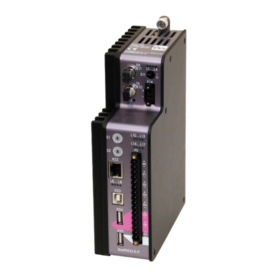
Page 14: Device Description
Manual ibaPADU-S-IT-16 Device description Views Operating status indicators L1 … L4 ON/OFF switch S11 Connector for power supply 24 V X14 Status LED digital inputs L10 … L17 Connection for digital inputs X5 Fixing screws Indicators L5 … L8 Network interface X22... -
Page 15: Indicator Elements
Disturbance, applications internal to the device do not run. Device failure (during start up) Important note When the LED L4 indicates a failure, please contact the iba Support. LEDs L5 … L8 7.2.2 The LEDs L5 … L8 have the following functions: ... -
Page 16: Status Of Digital Inputs L10
7.3.2 Rotary switches S1 and S2 With the S1 rotary switch, you can define the iba-FO-transfer protocol and the cascading addresses in the FO network: Position „0“: all previous ibaNet protocols (except 32Mbit Flex), only in cooperation with ibaLogic ... -
Page 17: System Function Pushbutton S10
11.1.7 “Deleting an ibaLogic program in ibaPADU-S-IT“ Communication interfaces 7.4.1 Connections FO cables X10 and X11 Process data between ibaPADU-S-IT-16 and the connected iba systems are transferred via FO cables. Using the 32Mbit Flex transfer protocol, also configuration data can be transferred via FO cable. Connection... -
Page 18: Debounce Filters
Manual ibaPADU-S-IT-16 Figure 4: Connection diagram for digital inputs X5 7.5.2 Debounce filters For the digital inputs, there are four debounce filters for each. These can be chosen and configured for each signal independently. You have got the following filters at your dispos- ... - Page 19 Manual „Stretch rising edge“ With the first rising edge, the input signal (red) switches to logical 1 and keeps this value for the defined debounce time. Thereafter, the channel is transparent again and waits for the next rising edge.
-
Page 20: Voltage Supply
Manual ibaPADU-S-IT-16 „Delay both edges“ Beginning with the first edge, the output signal (purple) blocks the input and keeps the log- ical value of the edge for the duration of the defined debounce time. Thereafter, the chan- nel is transparent again, directly assumes the logical level of the input signal and waits for the next edge –... -
Page 21: System Integration
Manual System integration Application examples The figures below show examples of ibaPADU-S-IT-16 combined with ibaPDA and ibaLogic. 8.1.1 Measuring systems with ibaPDA Figure 9: Measuring system with ibaPDA Pure measuring applications (capturing, recording, analyzing) Recording the signals with ibaPDA 8.1.2... -
Page 22: Standalone Systems With Ibalogic
Master control program on the ibaLogic PC Fast local control Fast deterministic communication via ibaNet to the central computer FO cascading With 32Mbit Flex, you can group up to 15 modular systems to a ring topology. Figure 13: Ring topology with ibaPADU-S-IT-16 Issue 1.10... -
Page 23: Supported Ibanet Transfer Protocols
A cascade can be formed with all devices that support the ibaNet 32Mbit Flex protocol. At the moment, these are the following devices: ibaBM-DDCS ibaBM-eCAT ibaBM-SiLink ibaPADU-S-CM ibaPADU-S-IT-16 Supported ibaNet transfer protocols Protocol Position of Min. telegram Max. signal Direction of Max. -
Page 24: Initial Start-Up
Manual ibaPADU-S-IT-16 Initial start-up Default settings As default settings, 2 user accounts and network parameters are pre-defined. As an ad- ministrator, you can change these settings. You can also set back the changed values to default settings. See chapter 9.1.4 “Set back to default settings“. -
Page 25: Set Back To Default Settings
Manual 9.1.4 Set back to default settings If you have changed the network settings or the passwords, and want to set them back to default values, please proceed as follows: 1. Switch off the device. 2. Position the rotary switches S1 on „6“ and S2 on „9“. - Page 26 IP address via „Control panel – Network connections“, e.g. 192.168.1.2 Note The IP address must not be 192.168.1.1, as this is the address of ibaPADU-S-IT-16. Use this IP address for accessing the Websites. 3. Start a Web browser on the PC and insert the IP address of the device in the URL: 192.168.1.1...
-
Page 27: Establishing Communication To The Device Via Fo Cable
Manual 9.2.2 Establishing communication to the device via FO cable We recommend this connection if the device has a 32Mbit Flex FO connection to ibaPDA. 1. Start ibaPDA and open the I/O Manager. See chapter 11.2.1 “Configuration in the I/O Manager“... -
Page 28: Network Settings On The Web Interface
Manual ibaPADU-S-IT-16 9.2.3 Network settings on the Web interface Important note If you do not get access to the Website under Windows 7 despite a connection is es- tablished, please change the security settings. See note in chapter 9.4.1 "Accessing the Website". - Page 29 Manual Procedure for setting a new fixed address: 1. Switch off the device by pressing S11. 2. Switch the rotary switches S1 to „F“ and S2 to „E". 3. Push the S10 pushbutton and keep it pressed (firmly up to the stop point) and then switch on the device again.
- Page 30 Manual ibaPADU-S-IT-16 In the following example, the network address 192.168.1.1 is set for the network inter- face X22: 1. L5 flashing Position S1 on „C “and S2 on „0“ and then press S10. 1. Octet number „192“ is set. 2. L5 lighted, L6 flashing: Set S1 on „A “and S2 on „8“...
-
Page 31: Time Settings
You can make the time settings only on the Website. Important note ibaPADU-S-IT-16 cannot store the time without external buffer voltage. If no supply voltage is connected to X14 or the device is switched off with the S11 switch, the device will lose the current time and restart with a default value. -
Page 32: Time Synchronization Of The Local Ibapadu-S-It-16 System
NTP protocol DCF77 NTP protocol You can set the ibaPADU-S-IT-16 internal system time via the NTP protocol, provided that an Ethernet connection (X22) is established to the Internet or a local NTP server. Figure 16: Time synchronization with NTP protocol 1. - Page 33 Manual DCF77 The ibaPADU-S-IT-16 internal system time can be synchronized on an external DCF77- clock. The DCF77 signal is fed in via any of the digital input channels. Figure 17: Setting the time by using DCF77 signal 1. Access the ibaPADU-S-system Website via the browser.
-
Page 34: Make Settings On The Website
Manual ibaPADU-S-IT-16 Important note This chapter describes how to synchronize the local time of an ibaPADU-S-IT-16 system. Other documentation Moreover, an additionally connected ibaPDA measuring system can be synchronized via any digital input (e.g. ibaPADU-S-IT-16 or a digital input module), please refer to ibaPDA-V6 manual. -
Page 35: Website Structure
Manual Other documentation There is a module specific Website for each I/O module. These are described in the manu- als for the single modules. The start page is displayed. On the start page, you can see the CPU and the plugged modules. - Page 36 Manual ibaPADU-S-IT-16 When clicking on a tab, you are asked to enter a valid user name and a password. You have got access to the tabs and settings, depending if you are logged in as “admin“ or “padu“. “Info“ tab 9.4.2.1...
- Page 37 Manual Note The “Overall release version“ refers to the whole ibaPADU-S system, including the mo- dules. When you get and install a new version, the CPU and all modules are updated. If you need support, please tell us the “Overall release version“.
- Page 38 Manual ibaPADU-S-IT-16 „network“ tab 9.4.2.5 On this tab, you can make as administrator changes in the network settings. Figure 24: “network“ tab You can adapt all network settings. WINS Devicename Here, you find the default host name. With this host name, you can access the device in the Webbrowser.
- Page 39 Manual “time“ tab 9.4.2.6 On the “time“ tab, you can change the time settings as “admin“. Description, see chapter 9.3 "Time settings" “update“ tab 9.4.2.7 On the “update“ tab, you can only as “admin“ transfer updates of the device software (Firmware) to the device and execute it.
- Page 40 <disable>: deactivating autostart Persistent Image Displaying if an ibaLogic program is stored on ibaPADU-S-IT-16, which can be started automatically triggered by autostart of the PMAC. 9.4.2.10 “notes“ tab On the “notes“ tab, you can enter notes, e.g. for notes on wiring or on recording of changes.
-
Page 41: Updates
Updates An update can be installed in two different ways: Web interface ibaPADU-S-IT-16 (also see chapter 9.4.2.7 “update“ tab) ibaPDA beginning with version 6.27.0 No matter which of the both ways you choose to install an update: the progress of the up- date is shown by the LEDs L5 …... -
Page 42: Update Via Ibapda
In this case, a new update file has to be installed for the “overall release version“. If you want to get the current update file, please contact the iba Support. You will also find it on the “ibaPADU-S Modular“ CD-ROM, included in delivery of the module. -
Page 43: Iba Applications
11.1 ibaLogic-V4 You can use ibaPADU-S-IT-16 – in cooperation with ibaLogic – for the following applica- tions: individual signal processing, control applications or stand-alone applications. ibaLogic programs can be loaded in the device as runtime versions and run there autono- mously. - Page 44 If there are other projects in this workspace, you need to “activate“ the new project. Configure ibaPADU-S-IT-16 as platform via the “Tools – Platform configuration“ menu. Figure 32: Start platform configuration For creating or configuring a platform, please click in the dialog under the project name on <New item>...
- Page 45 An alternative way for creating a platform is to open the “Current Platform” dropdown menu and select “Add platform”. If ibaPADU-S-IT-16 is configured as platform, yet, you can choose the platform via the dropdown box in the menu line. Figure 35: Choose platform in the menu line...
-
Page 46: Automatic Update Of The Ibalogic Version
Beginning with ibaLogic V4.2.4, the application verifies when configuring an ibaPADU-S-IT-16 platform or starting an ibaLogic program, whether the ibaLogic runtime version of ibaPADU-S-IT-16 is compatible to the ibaLogic version. If not, you are asked au- tomatically to update the ibaPADU-S-IT-16. -
Page 47: Configuring Signals
On the “Hardware Configuration“ tab, you can make the settings for ibaLogic and all avail- able resources. If ibaPADU-S-IT-16 is configured as platform, it is offered as Interrupt source only for ibaPADU-S-IT-16. Under “time base“, you set the smallest possible cycle time. The “Enable Watchdog“ func- tion is not released for ibaPADU-S-IT-16, yet. - Page 48 Manual ibaPADU-S-IT-16 Under “Module Settings“, ibaPADU-S-IT-16 is always activated. If “Buffered Access“ is enabled, the imported values are buffered and supplied to the pro- gram as Arrays. The smallest possible Interval of ibaLogic is 1 ms. If you want to measure signal values with sampling rates smaller than 1 ms, you need to record the signal values “buffered“.
- Page 49 Signal Settings for FiberOptics_IO module (FO interface) Figure 37: FO interface in the hardware configuration In the FiberOptics_IO module, you can define which FO transfer protocol ibaPADU-S-IT-16 uses for receiving and sending data. It depends on the FO protocol of the modules, which link protocol is needed.
- Page 50 Figure 38: Modular measuring system with intelligent pre-processing In the example above, “External” has to be chosen as FO protocol for input and output. The communication between ibaPADU-S-IT-16 and ibaPDA is done in the 32Mbit Flex mode. Figure 39: ibaLogic as module in ibaPDA...
- Page 51 Figure 40: Coupling of a modular I/O system to ibaPADU-S-IT-16 In the second example, the ibaNet750 I/O system is coupled to the iba-PADU-S system via 3.3Mbit. On the input side, you need to choose 3.3 Mbit as FO protocol. For this example, we did not configure an output.
- Page 52 In the program designer, you can define the evaluations or pre-processings and load the project into the “Programmable Measurement and Automation Controller“ (PMAC) on the ibaPADU-S-IT-16 CPU. Other documentation For a detailed description of the program designer and further information on processing, please refer to the ibaLogic manual.
-
Page 53: Dat_File_Write Function Block
11.1.4 DAT_FILE_WRITE function block Using a DAT_FILE_WRITE (DFW) function block data can be stored in the local memory of ibaPADU-S-IT-16. For this purpose the DFW function block has to be configured accord- ingly. Other documentation For a detailed description of the DFW function block and the usage please refer to the ibaLogic-V4 manual. -
Page 54: Configuring The Debounce Filter
Manual ibaPADU-S-IT-16 11.1.5 Configuring the debounce filter If you want to use debounce filters, these are made as configuration output and configured as Off-task connector (OTC) or function block. First, drag the output signals defined in the I/O configurator to the margin of the program- ming surface, in this example “X1_DebType_Ch00”... -
Page 55: Saving The Ibalogic Program On Runtime
PMAC in online mode. If Autostart is enabled on the „ibaLogic“ tab of the ibaPADU-S-IT-16 Website, the ibaLogic program is started automatically after you have switched on the device. -
Page 56: Deleting An Ibalogic Program In Ibapadu-S-It-16
Manual ibaPADU-S-IT-16 11.1.7 Deleting an ibaLogic program in ibaPADU-S-IT-16 If you want to delete an ibaLogic program from the device, please proceed as follows: 1. Switch off the device 2. Position the S1 rotary switch on „F“ and the S2 rotary switch on „C“. -
Page 57: Ibapda-V6
Start ibaPDA, open the I/O Manager and proceed as follows: 1. Look in the I/O Manager for the link of the FOB-D card, ibaPADU-S-IT-16 is connected to. Click with the right mouse button on the link. The submenu is opened. Choose “Au- todetect“. - Page 58 Manual ibaPADU-S-IT-16 2. If ibaPDA does not detect the device automatically, you can add the device manually. 3. Click with the right mouse button on the connection (Link) of the ibaFOB-io-D card, the device is connected to. 4. Choose “Add module“. The list of the available modules is displayed. Choose “ibaPADU-S-IT-16“.
-
Page 59: Padu-S - General Tab
A locked module can only be changed by an authorized user. Enabled Data capturing for this module is enabled. Name You can enter a name for the module. Timebase Specifies the time base for data capturing that is used for ibaPADU-S-IT-16 and the connected modules. Issue 1.10... -
Page 60: Padu-S - Diagnostics Tab
Manual ibaPADU-S-IT-16 Connection IP address The IP address or the host name of the ibaPADU-S-IT-16 device (only for infor- mation). Auto enable/disable When this option is enabled and ibaPDA cannot connect to this device during the start of the acquisition then it will disable this module and start the acquisition with- out it. -
Page 61: Padu-S - Analog Tab
Manual Reset to factory defaults Using this button all I/O settings that are made for this module with ibaPDA will be deleted after having confirmed the following request with <Yes>. Note The function “Reset to factory defaults” does not apply to the reset of network settings or passwords as described in chapter 9.1.4. -
Page 62: Padu-S - Digital Tab
Manual ibaPADU-S-IT-16 PADU-S – Digital tab 11.2.5 The “Digital“ tab appears when signal capturing with the digital input modules has been started. In the list, you can see the configured digital signals and the current values. Figure 52: PADU-S module – “Digital“ tab... -
Page 63: Ibapadu-S-It-16 - General Tab
Manual ibaPADU-S-IT-16 – General tab 11.2.6 Figure 53: ibaPADU-S-IT-16 module – “General“ tab Basic settings Locked, Enabled, Name, Timebase see chapter 11.2.2 “PADU-S – General tab “ Module No. Logical module number for clearly referencing the signals, e.g. when printing and for ibaAnalyzer. - Page 64 Manual ibaPADU-S-IT-16 Figure 54: ibaPADU-S-IT-16 module – Debug signals in the „Digital“ tab Analog debug signals are displayed in the analog tab: Figure 55: ibaPADU-S-IT-16 module – Debug signals in the „Analog“ tab Signal Meaning Analog Sample time (seconds) Time period since system start in seconds...
-
Page 65: Ibapadu-S-It-16 - Digital Tab
Manual ibaPADU-S-IT-16 – Digital tab 11.2.7 Figure 56: ibaPADU-S-IT-16 module – “Digital“ tab Name Here, you can enter a name for the signal and two additional comments (click on icon in the Name field). Debounce filter In the dropdown menu, you can choose the operating mode for the decounce filter. -
Page 66: Technical Data
24 V DC ± 10 % not stabilized, 1 A (without I/O modules), 3 A (with I/O modules) Power consumption Max. 20 W for ibaPADU-S-IT-16 Indicators 4 LEDs for operating status of the device 8 LEDs for status of the digital inputs... -
Page 67: Interfaces
Manual 12.2 Interfaces Interfaces ibaNet 3Mbit, 32Mbit, 32Mbit Flex 2x ST Lean connectors, FO (50/125 µm and 62.5/125 µm) for RX/TX max. cable length 500 m (32Mbit); 2000 m (3Mbit) Ethernet 10/100 Mbit/s 2x host, 1x device for service purposes 12.3... -
Page 68: Dimensions
Manual ibaPADU-S-IT-16 12.4 Dimensions ibaPADU-S-IT-16 (Dimensions in mm) Figure 57: Dimensions ibaPADU-S-IT-16 (Dimensions in mm) Figure 58: Dimensions ibaPADU-S-IT-16 with cables Issue 1.10... - Page 69 Manual Distance between 2 ibaPADU-S-IT-16 systems (Dimensions in mm) Figure 59: Min. distance between 2 ibaPADU-S-IT-16 systems Issue 1.10...
- Page 70 Manual ibaPADU-S-IT-16 ibaPADU-S-IT-16 and backplane (Dimensions in mm) Figure 60: Dimensions ibaPADU-S-IT-16 with backplane Issue 1.10...
- Page 71 Manual Mounting plate (Dimensions in mm) Figure 61: Dimensions of mounting plate Issue 1.10...
- Page 72 Manual ibaPADU-S-IT-16 Backplane ibaPADU-S-B4S with mounting angles (Dimensions in mm) Figure 62: Dimensions mounting angles with ibaPADU-S-B4S Backplane ibaPADU-S-B1S for one central unit and one module (Dimensions in mm) Figure 63: Dimensions ibaPADU-S-B1S Issue 1.10...
- Page 73 Manual (Dimensions in mm) Figure 64: Dimensions ibaPADU-S-B1S with modules Issue 1.10...
-
Page 74: Connection Diagram
Manual ibaPADU-S-IT-16 12.5 Connection diagram 12.5.1 Pin assignment voltage supply 24 V (X14) :X14 Pin… Connection + 24 V DC, voltage supply 12.5.2 Pin assignment digital inputs (X5) :X5 Pin… Connection Digital input 00 + Digital input 00 - Digital input 01 +... -
Page 75: Accessories And Related Products
Order number 10.124000 Backplane (can be mounted on the backside) for 1 ibaPADU-S-IT-16 and up to 4 I/O mod- ules w x h x d: 9.02 in x 8.62 in x 1.06 in (229 mm x 219 mm x 27 mm) - Page 76 Mounting panel 19“ for PADU-S modular Order number 10.124005 Mounting panel (483 mm/19“) for two backplanes Mounting 1 ibaPADU-S-IT-16 centered 2 ibaPADU-S-IT-16 left and right Installation equipment included in de- livery Module Carrier for ibaPADU-S modular system Order number 10.124007...
- Page 77 30.620480 For up to 2048 signals Online signal processing ibaLogic-V4 ibaLogic-V4 license already existing on ibaPADU-S-IT-16 for 64 inputs/outputs and DatFileWrite license ibaAnalyzer 33.010400 Offline- and online analysis software with free license if used to analyze *.dat files generated by licensed iba software.
-
Page 78: Appendix
Manual ibaPADU-S-IT-16 Appendix 14.1 Acronyms DHCP Dynamic Host Configuration Protocol Daylight Saving Time Fiber Optics Greenwich Mean Time Network Time Protocol PMAC Programmable Measurement and Automation Controller Real Clock Time TCP/IP Transmission Control Protocol / Internet Protocol Universal Time Coordinated... -
Page 79: Index
I/O Manager Timebase ibaLogic 39, 44 in ibaPDA assigning signals configuring signals ibaPADU-S-IT-16 as platform Update signal settings for FO interface modules ibaLogic-program via ibaPDA 42, 59 deleting 16, 17, 55 via Web interface... -
Page 80: Support And Contact
Koenigswarterstr. 44 90762 Fuerth Germany Phone: +49 911 97282-0 Fax: +49 911 97282-33 Email: iba@iba-ag.com Contact: Mr. Harald Opel Regional and Worldwide For contact data of your regional iba office or representative please refer to our Website www.iba-ag.com. Issue 1.10...
Need help?
Do you have a question about the ibaPADU-S-IT-16 and is the answer not in the manual?
Questions and answers