
Related Manuals for IBA FOB-SD


Summary of Contents for IBA FOB-SD
- Page 1 ibaFOB-SD Manual ibaFOB-SD Interface Board for Simadyn D Manual Issue 1.3 Issue 1.3...
- Page 2 Required corrections are contained in the following regulations or can be downloaded on the Internet. The current version is available for download on our web site http://www.iba-ag.com. Protection note Windows® is a label and registered trademark of the Microsoft Corporation. Other pro- duct and company names mentioned in this manual can be labels or registered trade- marks of the corresponding owners.
-
Page 3: Table Of Contents
ibaFOB-SD Manual Table of Contents About this manual.....................5 Target group ...................... 5 Notations ......................5 Symbols used ....................6 PC measurement system requirements............7 Hardware ......................7 Software ......................7 Safety information.....................7 Scope of delivery ....................8 Introduction .......................9 Application ......................9 Characteristics .................... - Page 4 Manual ibaFOB-SD 8.1.8 Tab Timing....................... 22 8.1.9 Tab Memory view .................... 22 Synchronization of more than one iba PCI card...........23 Important information ..................23 Procedure......................23 Technical data....................24 10.1 Main data ......................24 10.2 Performance of the ibaFOB-SD card/data load ..........25 Support and Contact..................27...
-
Page 5: About This Manual
ibaFOB-SD Manual About this manual This manual describes in detail the configuration and use of the product ibaFOB-SD. It serves both as a tutorial and a reference document. Target group This manual addresses in particular the qualified professionals who are familiar with handling electrical and electronic modules as well as communication and measurement technology. -
Page 6: Symbols Used
By an electric shock! Due to the improper handling of iba software products which are coupled to input and output procedures with control function! If you do not observe the safety instructions regarding the process and the system or... -
Page 7: Pc Measurement System Requirements
512 MB RAM or better >10 GB hard disk space Please see http://www.iba-ag.com for further details. Software Note Only the 32-bit versions of Windows operating systems are supported. Microsoft Windows NT 4.0 SP 5 (ibaPDA ≤V5) only, ... -
Page 8: Scope Of Delivery
Manual ibaFOB-SD Scope of delivery The following components are included with the delivery: ibaFOB-SD card Manual Synchronization cable (sync cable) For more accessories, not included in the scope of delivery, please refer to www.iba-ag.com. Issue 1.3... -
Page 9: Introduction
The ibaFOB-SD card couples the iba Process Data Acquisition system ibaPDA or the Soft PLC ibaLogic with the Siemens control system SIMADYN-D. Therefore, the iba- FOB-SD must be connected to one of the free fiber optic links of the SIMADYN-D CS12/13 or 14. -
Page 10: Remarks Concerning Simadyn-D
Manual ibaFOB-SD ibaPDA-Request-SD (former name Symbolic Request): Max. 4 boards with up to 50 µP connections (32 analog plus 32 digital signals each – a maximum of 1600 analog plus 1600 digital signals per card, depending on ibaPDA-V6 license); supports the ibaPDA-Technostring (a non-structured ASCII string) via the SD link. - Page 11 ibaFOB-SD Manual Figure 1: Example of configuration with ibaPDA Issue 1.3...
-
Page 12: Remarks On The Measurement Principle
To measure SIMADYN-D system numeric values must be transported between the SD system and the PC, which means that internal variables of the SD system may be visualized and recorded. For recording purposes 2 different software packages are provided by iba. Request-SD ... -
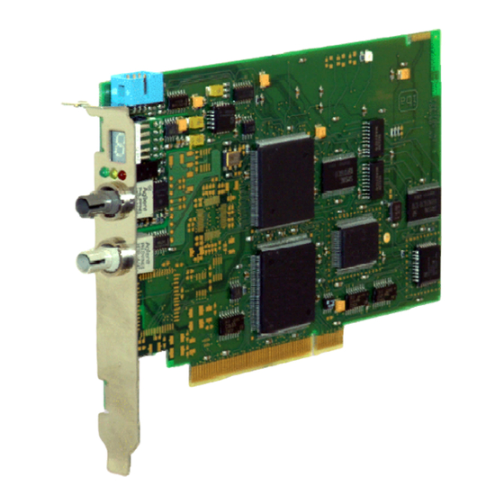
Page 13: Front View
ibaFOB-SD Manual Front view 1 7-segment display 2 Status LEDs 3 FO-connector (Receiver) 4 FO-connector (Transmitter) Figure 2 : Front view Plug and socket connections 1 Sync- connector (blue) Figure 3: Plug and socket connections Issue 1.3... -
Page 14: Indicators
Manual ibaFOB-SD Indicators 5.9.1 Device LEDs Run, Link and Error LEDs indicate the operational state of the ibaFOB-SD channels. The following table describes the states in which you may find the LEDs and their re- spective meanings. On power on all LEDs are on for a few seconds to prove their proper function. -
Page 15: Mounting And Dismounting
Plug in the card carefully into a free PCI slot. Fix the card to the housing of the PC. If more than one iba PCI card is installed connect all cards with one another by the flat ribbon cable (sync cable). -
Page 16: Dismounting
Manual ibaFOB-SD Dismounting Shut down the PC. Switch off the power supply of the PC. Unplug the mains power line. Open the PC so you can reach the PCI slots. Release the fixing screw. Unplug the card carefully out of the slot. Store the card in an appropriate con- tainer. -
Page 17: Software Configuration In Ibapda-V6
ibaFOB-SD Manual Software configuration in ibaPDA-V6 Other documentation For a more detailed description of the board’s configuration in ibaPDA-V6 please refer to the ibaPDA-V6 manual or online help and ibaPDA-Request-SD manual. If card has been installed correctly and the license is enabled in the dongle the card should be available in the I/O manager’s signal tree as a data interface. -
Page 18: Diagnosis In Ibapda-V6
Manual ibaFOB-SD Diagnosis in ibaPDA-V6 The essential tools for diagnosis are integrated in the I/O manager of ibaPDA-V6. General card diagnosis The image of the card as shown in chapter 7 provides essential information. The graphical representation of the card shows the animated displays and indicators of the real card. -
Page 19: Tab Processor Info
ibaFOB-SD Manual 8.1.2 Tab Processor Info This information about the DPR interface is for support purposes only. Here you can find the firmware version of the card. Figure 6: Processor information 8.1.3 Tab Report control Here you'll find information about the connection and telegram traffic of the up to 50 PDA channels. -
Page 20: Tab Command/Acknowledge
Manual ibaFOB-SD 8.1.4 Tab Command/Acknowledge Here, you'll find information about the command and acknowledge handshake during telegram traffic of the up to 50 PDA channels. Figure 8: Command / Acknowledge 8.1.5 Tab Data control Here you'll get information about the data traffic of the up to 50 PDA channels. Figure 9: Data control Issue 1.3... -
Page 21: Tab Configuration
ibaFOB-SD Manual 8.1.6 Tab Configuration Here you find information about the CS14 report area, where the connected BGTs are registered. Figure 10: Configuration 8.1.7 Tab Channels Here, you get information about the CS14 board and the configured communication channels. Figure 11: Channels Issue 1.3... -
Page 22: Tab Timing
8.1.8 Tab Timing Here, you'll find information about the FOB-SD load and access statistic. The firmware ibaFOB-SD provides a statistical log of all SD accesses. Primarily this feature has been added as a helper for the software development and optimization. But a user may use the information as well for a better configuration of the SD. -
Page 23: Synchronization Of More Than One Iba Pci Card
Always save your system configuration before changing hardware components. Procedure You should perform the following steps after you’ve installed the PCI card: Connect all iba PCI cards with the synchronization cable using the blue plugs. Figure 14: Connecting multiple iba PCI cards by sync cable Close the PC. -
Page 24: Technical Data
Manual ibaFOB-SD Technical data 10.1 Main data Order No. 11.112700 Format/size Short PCI card ° ° Operating Temperature From 32 °F to 122 °F (from 0 C to 50 ° ° Storage Temperature From -13 °F to 158 °F (from -25 C to 70 °... -
Page 25: Performance Of The Ibafob-Sd Card/Data Load
ibaFOB-SD Manual 10.2 Performance of the ibaFOB-SD card/data load Note Valid with firmware B5 or higher. Extract from a test protocol ibaPDA No. of channels Measured efficiency % Measured efficiency % Sample time (32 analog + 32 digital signals without Techno string with Techno string (ms) each) - Page 26 Manual ibaFOB-SD Figure 15: Relation between sample time and number of channels (TS: Technostring) Reading help (example): At a sample time of 8 ms (ibaPDA) it’s possible to process up to 30 channels with Technostring and 31 channels without Technostring at an accept- able efficiency.
-
Page 27: Support And Contact
Koenigswarterstr. 44 90762 Fuerth Germany Phone: +49 911 97282-0 Fax: +49 911 97282-33 E-Mail: iba@iba-ag.com Contact: Mr. Harald Opel Regional and Worldwide For contact data of your regional iba office or representative please refer to our web site www.iba-ag.com. Issue 1.3...
Need help?
Do you have a question about the FOB-SD and is the answer not in the manual?
Questions and answers