
Subscribe to Our Youtube Channel
Related Manuals for Metrologic Orbit MS7100


Summary of Contents for Metrologic Orbit MS7100
- Page 1 METROLOGIC INSTRUMENTS, INC. MS7100 Series Fixed Projection Laser Scanner Installation and User’s Guide MLPN 2408 Printed in USA October 1998...
- Page 2 Copyright ® © 1998 by Metrologic Instruments, Inc. All rights reserved. No part of this work may be reproduced, transmitted, or stored in any form or by any means without prior written consent, except by reviewer, who may quote brief passages in a review, or provided for in the Copyright Act of 1976.
-
Page 3: Table Of Contents
Scanner and Accessories ........ - Page 4 Appendix A Design Specifications 27, 28 Appendix B Default Settings 29-32 Appendix C Pin Assignments 33-35 Appendix D Warranty and Disclaimer 36, 37 Appendix E Notices 38, 39 Index 40, 41...
-
Page 5: Introduction
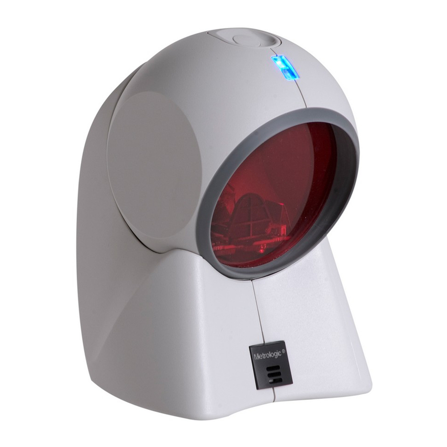
Orbit is small in size, but BIG in performance. Designed for applications where counter space is limited, Orbit is the ideal presentation scanner for retail, convenience, liquor and specialty stores. In addition, Orbit’s unique, contoured shape allows it to be picked-up and used as a hand-held scanner when scanning large or bulky items. -
Page 6: Scanner And Accessories
Scanner and Accessories following is a list of the parts included in the MS7100 kit. MS7100 Hand-Held Laser Scanner - Refer to page 26 for available communication protocols Power Transformer AC in 120V, 220V- 240V Continental European or 220V- 240V UK. DC in regulates 5.2V@650mA (MLPN45593/45591/45592) MLPN 2408 User’s and Installation Guide... -
Page 7: Quick Start
Quick Start 1.) Plug in the scanner. When the MS7100 is ready to scan, the red LED will turn on, then the green LED will flash and the scanner will beep once. (the green LED will remain on for the duration of the beep). -
Page 8: Operational Test
Operational Test Metrologic recommends using the external power supply provided with the scanner when operating the MS7100. When using power supplied by the host, the host system should supply a minimum of 250 mA of current @ 5VDC. Keyboard Wedge Scanners: Connect the 10-pin modular plug of the PowerLink cable into the scanner jack. -
Page 9: Scanner Installation: Powered By External Power Supply
Then the scanner will beep once and the green LED will flash simultaneously. b. Plugging the scanner into the serial port of the PC does not guarantee that scanned information will appear at the PC. A software driver and correct configuration setting are also... -
Page 10: Scanner Installation: Powered By The Host Device
Scanner Installation: Powered by Host Device The MS7100 scanner interfaces terminate to a 10-pin modular jack. Connect the 10-pin modular plug of the PowerLink cable into the jack then connect the other end of the PowerLink cable to the host. Refer to Appendix C page 33 for pin assignments. -
Page 11: Scanner Installation To The Pc For The Scanner With Built-In Pc Keyboard Wedge Interface
SELV (Safety Extra Low Voltage) according to EN 60950. 1. The MS7100 Keyboard Wedge scanner interface terminates to a 10-pin modular jack. Connect the 10-pin modular plug of the PowerLink cable into the jack. The Power Link cable is terminated with a 5-pin DIN female connector on one end, and a 6-pin mini DIN male on the other. -
Page 12: Scanner Parts
Green and Red LEDs: When the red LED is on, this indicates that the laser is on. When the green LED flashes on, the scanner has read a bar code successfully. When the green light turns off, communication to the host is complete. The LEDs are also used as diagnostic indicators and mode indicators. -
Page 13: Audible Indicators
Audible Indicators When the MS7100 scanner is in operation, it provides audible feedback. These sounds indicate the status of the scanner. Eight settings are available for the tone of the beep (normal, 6 alternate tones and no tone). To change the tone, refer to the MetroSelect Programming Guide MLPN 2407. -
Page 14: Failure Modes
Return the unit for repair at an authorized service center. Three Beeps - on power up If the scanner beeps 3 times on power up then, the non- volatile memory that holds the scanner configuration has failed. Return the unit for repair at an authorized... -
Page 15: Visual Indicators
Visual Indicators There are a red LED and a green LED on the head of the Orbit MS7100. When the scanner is on, the flashing or stationary activity of the LEDs indicates the status of the current scan and the scanner. -
Page 16: Labels
Labels Each scanner has labels on the bottom of the unit. One label contains information such as the model number, date of manufacture, serial number and notes that the device is a Class IIa laser product. The other label states the device is an LASERKLASSE 1 product. -
Page 17: Depth Of Field Specifications
Depth of Field Specifications (based on 100% UPC bar codes) Optimal Depth of Field (default) Close Depth of Field... -
Page 18: Normal Depth Of Field
Normal Depth of Field Far Depth of Field... -
Page 19: Minimum Bar Code Element From Scanner Face
Depth of Field by Minimum Bar Code Element Width Optimal Depth of Field (default) -
Page 20: Close Depth Of Field
Close Depth of Field... -
Page 21: Normal Depth Of Field
Normal Depth of Field... -
Page 22: Far Depth Of Field
Far Depth of Field... -
Page 23: Maintenance
Maintenance Smudges and dirt can interfere with the proper scanning of a bar code. Therefore, the output window will need occasional cleaning. 1. Spray glass cleaner onto lint free, non-abrasive cleaning cloth. 2. Gently wipe the scanner window. -
Page 24: Troubleshooting Guide
The following guide is for reference purposes only. Contact a Metrologic representative at 1-800-ID-METRO or 1-800-436-3876 to preserve the limited warranty terms on page 36. All Interfaces MS7100 Series Troubleshooting Guide SYMPTOMS POSSIBLE CAUSE(S) No LEDs, beep No power is being supplied... - Page 25 4 character bar code) SYMPTOM The scanner scans a bar code but the scanner locks up (green LED comes on and stays on) after the first scan POSSIBLE CAUSE(S) The scanner is configured to support...
- Page 26 SYMPTOM Scanner beeps at some bar codes and NOT for others of the same bar code symbology POSSIBLE CAUSE(S) The print quality of the bar code is Check print mode. The type of printer could suspect be the problem. Change print settings. For...
- Page 27 The unit scans the bar code but there is no data POSSIBLE CAUSE(S) Configuration is not correct Make sure the scanner is configured for the appropriate mode. Check internal jumper SYMPTOM The unit scans but the data is not correct...
- Page 28 The host is receiving data but the data does not look correct POSSIBLE CAUSE(S) The scanner and host may not be Check that the scanner and the host are configured for the same interface font configured for the same interface font...
- Page 29 This program is for demonstration purposes only. It is only intended to prove that cabling is correct, the com port is working, and the scanner is working. If the bar code data displays on the screen while using this program, it only demon-strates that the hardware interface and scanner are working.
-
Page 30: Application And Protocols
OCIA ready (OCIA) 7100 IBM 46XX/RS-232 ready (IBM) The MS7100 Hand-Held Laser Scanner with Built-in PC Keyboard Wedge Interface is designed to be used for keyboard emulation only. However, many RS-232 programmable functions that are available in other Metrologic scanners are also available as keyboard wedge functions. -
Page 31: Design Specifications
Appendix A Design Specifications Operational Light Source: VLD 675 ± 5nm, 0.681 milliwatts ( Depth of Field: (0" to 8.5") at default 0 mm to 215 mm (programmable) Scan Speed: 1200 scans/second Scan Pattern: 5 fields of 4 parallel lines (omnidirectional) Scan Lines: Min Bar Width: 0.13 mm (5.2 mil) - Page 32 Electrical Input Voltage: 5.2VDC ± 0.25V Power : 1.1 W Operating Current : 225 mA DC Transformers: Class II; 5.2 V @650 mA Laser Class: CDRH: Class IIa; EN 60 825-1: 1994/A11:1996 Class 1 EMC: FCC Class A, CISPR Class A Environmental Operating Temperature: 0EC to 40EC (32EF to 104EF)
-
Page 33: Default Settings
The scanner is shipped from the factory programmed to a set of default conditions. The default parameter of the scanner has an asterisk ( * ) in the charts on the following pages. If an asterisk is not in the default column then the default setting is Off or Disabled. - Page 34 Parameter Default OCIA 232* DTS/NIXDORF NCR F NCR S Poll Light Pen Source Beeper Tone Normal Beep/Transmit Sequence Before Transmit Communication Timeout None Razzberry Tone on Timeout Three Beeps on Timeout No Beeps on Timeout Enter Power Save Mode 10 mins. Same Symbol Rescan Timeout: 200 msecs Same Symbol Rescan...
- Page 35 Parameter Default OCIA Light 232* Transmit Codabar Start/Stop Characters CLSI Editing (Enable) Transmit Mod 43 Check Digit on Code 39 Transmit Code 39 Stop/Start Characters Transmit Mod 10/ITF Transmit MSI-Plessey Check Characters Parity Space Baud Rate 9600 8 Data Bits 7 Data Bits Transmit Sanyo ID Characters Nixdorf ID...
- Page 36 Parameter Default OCIA 232* Two Digit Supplements Five Digit Supplements Bookland 977 (2 digit) Supplemental Requirement Supplements are not Required Two Digit Redundancy Five Digit Redundancy 100 msec to Find Supplement Programmable in 100msec steps (MAX 800 msec) Coupon Code 128 Programmable Code Lengths 7 aval.
-
Page 37: Pin Assignments
Pin Assignments Pin Assignments for the PowerLink Cable The MS7100 scanner interfaces terminate to a 10-pin modular jack. Connect the 10-pin modular plug of the PowerLink cable into the jack then connect the other end of the PowerLink cable to the host. (Refer to page 6 for details). - Page 38 Pin Assignments for the PowerLink Cable Keyboard Wedge Interface The MS7100 Keyboard Wedge scanner interface terminates to a 10-pin modular jack. Connect the 10-pin modular plug of the PowerLink cable into the jack then connect the other end of the PowerLink Y-type cable to the host and keyboard (refer to page 7 for details).
-
Page 39: Pin Assignments
Pin Assignments for the 5-pin DIN and 6-pin mini-DIN MS7100 Hand- Held Laser Scanner with Built-in PC Keyboard Wedge Interface The MS7100 Keyboard Wedge scanner interface terminates to a 10-pin modular jack. Connect the 10-pin modular plug of the PowerLink cable into the jack. -
Page 40: Warranty And Disclaimer
DAMAGES, INCLUDING, WITHOUT LIMITATION, ANY INJURY TO PROPERTY OR PERSON OR EFFECT ON BUSINESS OR PROFIT, AND IN NO EVENT SHALL ANY LIABILITY OF METROLOGIC EXCEED THE ACTUAL AMOUNT PAID TO METROLOGIC FOR THE PRODUCT. Metrologic Instruments, Inc. Customer Service Department 90 Coles Road 1-800-ID-METRO... - Page 41 Disclaimer Metrologic Instruments, Inc. and the author or authors make no claims or warranties with respect to the contents or accuracy of this publication, or the product it describes, including any warranties of fitness or merchantability for a particular purpose. Any stated or expressed warranties are in lieu of all obligations or liability for any damages, whether special, indirect, or consequential, arising out of or in connection with the use of this publication or the product it describes.
-
Page 42: Notices
Under no circumstances should the customer attempt to service the laser scanner. Never attempt to look at the laser beam, even if the scanner appears to be nonfunctional. Never open the scanner in an attempt to look into the device. Doing so could result in hazardous laser light exposure. - Page 43 Umständen versuchen, den Laser-Scanner selbst zu warten. Sehen Sie niemals in den Laserstrahl, selbst wenn Sie glauben, daß der Scanner nicht aktiv ist. Öffnen Sie niemals den Scanner, um in das Gerät hineinzusehen. Wenn Sie dies tun, können Sie sich einer lebensgefährlichen Laserstrahlung aussetzen.
-
Page 44: Index
Index Accessories Disclaimer AC input/outlet 2, 4, 5, 7 Adapter Electrical cable 2, 7, 35 External power supply Approvals 7, 33, 34 Assignments 33-35 Audible indicators Failure indicator(s) Authorized service center 36 Failure modes Autodiscriminates Female connector 2, 7, Function(s) Bar code 3, 8, 9, 11, 13, 15, 19, 21-23, 25, 27... - Page 45 RS-232 1-6, 24-27, 33, 34 Min bar width Scan lines Normal depth of field 14, 17 Scan pattern(s) Notices 38, 39 Scan speed Scanner installation SELV OCIA 1, 2, 4, 6, 26, 27, 33 Service 36 Operating current 28 Shock Operating temperature...
Need help?
Do you have a question about the Orbit MS7100 and is the answer not in the manual?
Questions and answers