
Related Manuals for Metrologic MS7120 Series


Summary of Contents for Metrologic MS7120 Series
- Page 1 METROLOGIC INSTRUMENTS, INC. MS7120 Series Fixed Projection Laser Scanner Installation and User’s Guide MLPN 2408 Printed in USA December 1998...
- Page 2 Copyright ® © 1998 by Metrologic Instruments, Inc. All rights reserved. No part of this work may be reproduced, transmitted, or stored in any form or by any means without prior written consent, except by reviewer, who may quote brief passages in a review, or provided for in the Copyright Act of 1976.
-
Page 3: Table Of Contents
Table of Contents Introduction ........... 1 Scanner and Accessories . - Page 4 Table of Contents (continued) Appendix A Design Specifications 29, 30 Appendix B Default Settings 31-35 Appendix C Pin Assignments 36-38 Appendix D Warranty and Disclaimer 39, 40 Appendix E Notices 41, 42 Index 43, 44...
-
Page 5: Introduction
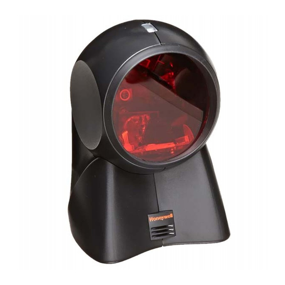
Introduction Orbit™ is an aggressive, omnidirectional laser bar code scanner. Light-weight and rugged, Orbit is small in size, but BIG in performance. Designed for applications where counter space is limited, Orbit is the ideal presentation scanner for retail, convenience, liquor and specialty stores. In addition, Orbit’s unique, contoured shape allows it to be picked-up and used as a hand-held scanner when scanning large or bulky items. -
Page 6: Scanner And Accessories
Scanner and Accessories following is a list of the parts included in the MS7100 kit. MS7120 Laser Scanner - Refer to page 28 for available communication protocols Power Transformer AC in 120V, 220V- 240V Continental European or 220V- 240V UK. DC in regulates 5.2V@650mA (MLPN45593/45591/45592) RS-232, Light Pen, OCIA and 46xx scanners: PowerLink cable with built in power jack:... -
Page 7: Quick Start
Quick Start 1.) Plug in the scanner. When the MS7120 is ready to scan, the green LED will turn on, then the red LED will flash and the scanner will beep once. (the red LED will remain on for the duration of the beep). 2.) The scanner is shipped from the factory programmed with default settings. -
Page 8: Operational Test
Operational Test Metrologic recommends using the external power supply provided with the scanner when operating the MS7120. When using power supplied by the host, the host system should supply a minimum of 250 mA of current @ 5VDC. Keyboard Wedge Scanners: Connect the 10-pin modular plug of the PowerLink cable into the scanner jack. -
Page 9: Scanner Installation: Powered By External Power Supply
Scanner Installation: Powered by External Power Supply To maintain compliance with applicable standards, all circuits connected to the scanner must meet the requirements for SELV (Safety Extra Low Voltage) according to EN 60950. 1. Turn off the host system. 2. Make the necessary PowerLink cable connections to the scanner and the host. -
Page 10: Scanner Installation: Powered By The Host Device
Scanner Installation: Powered by Host Device The MS7120 scanner interfaces terminate to a 10-pin modular jack. Connect the 10-pin modular plug of the PowerLink cable into the jack then connect the other end of the PowerLink cable to the host. Refer to Appendix C page 36 for pin assignments. -
Page 11: Scanner Installation To The Pc For The Scanner With Built-In Pc Keyboard Wedge Interface
Scanner Installation to the PC for the Scanner with Built-in PC Keyboard Wedge Interface To maintain compliance with applicable standards, all circuits connected to the scanner must meet the requirements for SELV (Safety Extra Low Voltage) according to EN 60950. 1. -
Page 12: Scanner Parts
Scanner Parts Green and Red LEDs: During normal operation, the green LED is on. This indicates that the laser is on and the unit is ready to scan. On a successful read of a bar code, the red LED will turn on. After communication to the host is complete, the red LED will turn off. -
Page 13: Audible Indicators
Audible Indicators When the MS7120 scanner is in operation, it provides audible feedback. These sounds indicate the status of the scanner. Eight settings are available for the tone of the beep (normal, 6 alternate tones and no tone). To change the tone, refer to the MetroSelect Programming Guide MLPN 2407. -
Page 14: Failure Modes
Failure Modes Flashing Green and One Razzberry Tone This indicates the scanner has experienced a laser subsystem failure. Return the unit for repair at an authorized service center. Flashing Red and Green and Two Razzberry Tones This indicates the scanner has experienced a motor failure. -
Page 15: Visual Indicators
Visual Indicators There are a red LED and a green LED on the head of the Orbit MS7120. When the scanner is on, the flashing or stationary activity of the LEDs indicates the status of the current scan and the scanner. No Red or Green LED The LEDs will not be illuminated if the scanner is not receiving power from the host or transformer. -
Page 16: Labels
Labels Each scanner has labels on the bottom of the unit. One label contains information such as the model number, date of manufacture, serial number and notes that the device is a Class IIa laser product. The other label states the device is an LASERKLASSE 1 product. -
Page 17: Depth Of Field Specifications
Depth of Field Specifications (based on 100% UPC bar codes) Optimal Low Density Depth of Field (default) Optimal High Density Depth of Field... -
Page 18: Close Depth Of Field
Depth of Field Specifications (continued) (based on 100% UPC bar codes) Close Depth of Field Normal Depth of Field... -
Page 19: Far Depth Of Field
Depth of Field Specifications (continued) (based on 100% UPC bar codes) Far Depth of Field... -
Page 20: Minimum Bar Code Element From Scanner Face
Depth of Field by Minimum Bar Code Element Width Optimal Low Density Depth of Field (default) -
Page 21: Optimal High Density Depth Of Field
Depth of Field by Minimum Bar Code Element Width (continued) Optimal High Density Depth of Field (default) -
Page 22: Close Depth Of Field
Depth of Field by Minimum Bar Code Element Width (continued) Close Depth of Field... -
Page 23: Normal Depth Of Field
Depth of Field by Minimum Bar Code Element Width (continued) Normal Depth of Field... -
Page 24: Far Depth Of Field
Depth of Field by Minimum Bar Code Element Width (continued) Far Depth of Field... -
Page 25: Maintenance
Maintenance Smudges and dirt can interfere with the proper scanning of a bar code. Therefore, the output window will need occasional cleaning. 1. Spray glass cleaner onto lint free, non-abrasive cleaning cloth. 2. Gently wipe the scanner window. -
Page 26: Troubleshooting Guide
Troubleshooting Guide The following guide is for reference purposes only. Contact a Metrologic representative at 1-800-ID-METRO or 1-800-436-3876 to preserve the limited warranty terms on page 39. All Interfaces MS7120 Series Troubleshooting Guide SYMPTOMS POSSIBLE CAUSE(S) SOLUTION No LEDs, beep No power is being supplied Check transformer, outlet and power or motor spin... - Page 27 Troubleshooting Guide (continued) SYMPTOMS POSSIBLE CAUSE(S) SOLUTION The unit powers Beeper disabled. No tone Enable beeper. Select tone up, but does not selected scan and/or beep The unit powers Scanning a particular UPC/EAN, Code 39, interleaved 2 of up, but does not symbology that is not 5, Code 93, Code 128 and Codabar scan and/or beep...
- Page 28 Troubleshooting Guide (continued) SYMPTOMS POSSIBLE CAUSE(S) SOLUTION Scanner beeps at The print quality of the bar Check print mode. The type of printer some bar codes code is suspect could be the problem. Change print and NOT for settings. For example change to econo others of the mode or high speed same bar code...
- Page 29 Troubleshooting Guide (continued) Keyboard Wedge Only SYMPTOMS POSSIBLE CAUSE(S) SOLUTION The unit scans Configuration is not Make sure the scanner is configured the bar code but correct for the appropriate mode. Check there is no data internal jumper The unit scans Configuration is not Make sure that the proper PC type AT, but the data is...
-
Page 30: Troubleshooting Guide
Troubleshooting Guide (continued) RS-232 only SYMPTOMS POSSIBLE CAUSE(S) SOLUTION Power-up OK Com port at the host is not Check to make sure that the baud rate and scans OK working or configured and parity of the scanner and the but does not properly communication port match and the communicate... -
Page 31: Rs-232 Demonstration Program
RS-232 Demonstration Program If an RS-232 scanner is not communicating with your IBM compatible PC, key in the following BASIC program to test that the communication port and scanner are working. This program is for demonstration purposes only. It is only intended to prove that cabling is correct, the com port is working, and the scanner is working. -
Page 32: Application And Protocols
Applications and Protocols The model number on each scanner includes the scanner number and communications protocol. Scanner Version Identifier Communication Protocol(s) 7120 Full RS-232C and Light Pen Emulation 7120 Keyboard Wedge, Stand-Alone Keyboard and RS-232 Transmit/Receive 7120 OCIA and RS-232 Transmit/Receive 7120 IBM 46XX and Full RS-232C 7120... -
Page 33: Design Specifications
Appendix A Design Specifications Operational Light Source: VLD 675 ± 5nm, 0.681 milliwatts ( PEAK Depth of Field: (0" to 8.5") at default 0 mm to 215 mm (programmable) Scan Speed: 1200 scans/second Scan Pattern: 5 fields of 4 parallel lines (omnidirectional) Scan Lines: Min Bar Width: 0.13 mm (5.2 mil) - Page 34 Appendix A (continued) Electrical Input Voltage: 5.2VDC ± 0.25V Power : 1.1 W Operating Current : 225 mA DC Transformers: Class II; 5.2 V @650 mA Laser Class: CDRH: Class IIa; EN 60 825-1: 1994/A11:1996 Class 1 EMC: FCC Class A, CISPR Class A Environmental Operating Temperature: 0EC to 40EC (32EF to 104EF)
-
Page 35: Appendix B Default Settings
Appendix B Default Settings Many functions of the scanner can be "programmed" - that is, enabled or disabled. The scanner is shipped from the factory programmed to a set of default conditions. The default parameter of the scanner has an asterisk ( * ) in the charts on the following pages. - Page 36 Appendix B (continued) Parameter Default OCIA Light 232* 46XX DTS/NIXDORF NCR F NCR S Poll Light Pen Source Beeper Tone Normal Beep/Transmit Sequence Before Transmit Communication Timeout None Razzberry Tone on Timeout Three Beeps on Timeout No Beeps on Timeout Enter Power Save Mode 10 mins.
- Page 37 Appendix B (continued) Parameter Default OCIA Light 232* 46XX Transmit UPC-A Item ID# Transmit Codabar Start/Stop Characters CLSI Editing (Enable) Transmit Mod 43 Check Digit on Code 39 Transmit Code 39 Stop/Start Characters Transmit Mod 10/ITF Transmit MSI-Plessey Check Characters Parity Space Baud Rate...
- Page 38 Appendix B (continued) Parameter Default OCIA Light 232* 46XX Character RTS/CTS Message RTS/CTS XON/XOFF Handshaking ACK/NAK Two Digit Supplements as code Five Digit Supplements as code Bookland as code 977 (2 digit) Supplemental Requirement Supplements are not Required Two Digit Redundancy Five Digit Redundancy 100 msec to Find Supplement Programmable in 100msec...
- Page 39 Appendix B (continued) Parameter Default OCIA Light 232* 46XX Normal Depth of Field Extended Depth of Field Long Depth of Field Ultra Close Depth of Field...
-
Page 40: Appendix C Pin Assignments
Appendix C Pin Assignments Pin Assignments for the PowerLink Cable The MS7120 scanner interfaces terminate to a 10-pin modular jack. Connect the 10-pin modular plug of the PowerLink cable into the jack then connect the other end of the PowerLink cable to the host. (Refer to page 6 for details). - Page 41 Appendix C (continued) Pin Assignments for the PowerLink Cable Keyboard Wedge Interface The MS7120 Keyboard Wedge scanner interface terminates to a 10-pin modular jack. Connect the 10-pin modular plug of the PowerLink cable into the jack then connect the other end of the PowerLink Y-type cable to the host and keyboard (refer to page 7 for details).
-
Page 42: Pin Assignments
Appendix C (continued) Pin Assignments for the 5-pin DIN and 6-pin mini-DIN MS7120 Hand- Held Laser Scanner with Built-in PC Keyboard Wedge Interface The MS7120 Keyboard Wedge scanner interface terminates to a 10-pin modular jack. Connect the 10-pin modular plug of the PowerLink cable into the jack. -
Page 43: Warranty And Disclaimer
DAMAGES, INCLUDING, WITHOUT LIMITATION, ANY INJURY TO PROPERTY OR PERSON OR EFFECT ON BUSINESS OR PROFIT, AND IN NO EVENT SHALL ANY LIABILITY OF METROLOGIC EXCEED THE ACTUAL AMOUNT PAID TO METROLOGIC FOR THE PRODUCT. Metrologic Instruments, Inc. Customer Service Department 90 Coles Road 1-800-ID-METRO... - Page 44 Appendix D (continued) Disclaimer Metrologic Instruments, Inc. and the author or authors make no claims or warranties with respect to the contents or accuracy of this publication, or the product it describes, including any warranties of fitness or merchantability for a particular purpose. Any stated or expressed warranties are in lieu of all obligations or liability for any damages, whether special, indirect, or consequential, arising out of or in connection with the use of this publication or the product it describes.
-
Page 45: Appendix E Notices
Appendix E Notices Notice This equipment has been tested and found to comply with limits for a Class A digital device, pursuant to Part 15 of the FCC Rules. These limits are designed to provide reasonable protection against harmful interference when the equipment is operated in a commercial environment. This equipment generates, uses and can radiate radio frequency energy and, if not installed and used in accordance with the instruction manual, may cause harmful interference to radio communications. - Page 46 Appendix E (continued) Anmerkung Nach Überprüfung dieses Geräts wurde festgestellt, daß es den Grenzwerten für Digitalgeräte der Klasse A gemäß Teil 15 der Richtlinien der US-amerikanischen Bundesbehörde für das Fernmeldewesen entspricht. Diese Grenzwerte wurden festgelegt, um einen angemessenen Schutz gegen schädliche Auswirkungen bei Einsatz des Geräts in einer Ladenumgebung zu gewähren. Das Gerät erzeugt und verwendet Hochfrequenzenergie und kann diese ausstrahlen, und kann, falls es nicht gemäß...
-
Page 47: Index
Index Accessories Disclaimer AC input/outlet 2, 4, 5, 7 Adapter Electrical cable 2, 7, 38 External power supply 4, 5, Approvals 7, 36, 37 Assignments 36-38 Audible indicators Failure indicator(s) 9, 10, Authorized service center 39 Failure modes 9, 10 Autodiscriminates Female connector 2, 7, Function(s) - Page 48 Index (continued) Razzberry tone 9-11 Light Pen 1, 2, 4, 6, 28, RDATA 36 Recommendation 7 Light source Red led 3-6, 8, 9, 11, 23 List Repair 10, 39 Rights property Maintenance warranty Manufacturer’s recommendation Roll, pitch, yaw Mechanical RS-232 1-6, 26-29, 36, 37 Min bar width Scan lines Normal depth of field...
Need help?
Do you have a question about the MS7120 Series and is the answer not in the manual?
Questions and answers