
Related Manuals for Metrologic MS7820 Solaris


Summary of Contents for Metrologic MS7820 Solaris
- Page 1 METROLOGIC INSTRUMENTS, INC. MS7820 Solaris™ Bar Code Scanner Installation and User’s Guide...
- Page 2 Copyright © 2008 by Metrologic Instruments, Inc. All rights reserved. No part of this work may be reproduced, transmitted, or stored in any form or by any means without prior written consent, except by reviewer, who may quote brief passages in a review, or provided for in the Copyright Act of 1976.
-
Page 3: Table Of Contents
Cable Installation (Interface Specific) ............. 12 Keyboard Wedge..................12 USB......................13 RS232 ......................14 IBM 46xx ..................... 15 Cable Installation (Secondary Metrologic Scanner) ........16 EAS Deactivation.................... 19 Flex Stand Installation, MLPN 46-00868............20 Wall Mount Stand Installation, MLPN 46-00869 ..........23 CANNER PERATION Scan Zone ...................... - Page 4 ABLE OF ONTENTS Power Save Modes..................36 Touch Button Panel ..................37 AINTENANCE Replaceable Protective Outer Window ............38 Daily Maintenance ..................38 ROUBLESHOOTING UIDE Troubleshooting Symptom / Solution Chart ............ 39 ................44 ONFIGURATION ODES ...............45 PGRADING THE IRMWARE CANNER AND ABLE ERMINATIONS Scanner Pinout Connection ................
-
Page 5: Product Overview
NTRODUCTION RODUCT VERVIEW Metrologic’s MS7820 Solaris™ vertical mini-slot scanner increases productivity with an unmatched feature set that aggressively scans high-density codes and fits easily into any existing enclosure found in small item, high-volume retail environments. Every scanner comes standard with an integrated RF EAS antenna, Checkpoint and Sensormatic interlock and the ability to be remotely configured or Flash upgraded. -
Page 6: Applications And Protocols
The MS7820 bar code scanner with Built-in PC Keyboard Wedge Interface is designed to be used for keyboard emulation only. Many RS232 configurable functions available in other Metrologic scanners are also available as keyboard wedge functions. The following are the most important selectable options specific to the keyboard wedge. -
Page 7: Scanner And Accessories
00-02283 MS7820 Bar Code Scanner Installation and User’s Guide 57-57312-3 MS7820 EAS Cable - Checkpoint (External) 57-57313-3 MS7820 EAS Cable - Sensormatic (External) Guides also available for download at www.metrologic.com. PTIONAL CCESSORIES Part # Description MS7820 Scanner Interface Cables 5S-5S... -
Page 8: Optional Accessories
** For 7800 Replacement Protective Outer Window removal / installation instructions see page 38 of this manual. Other items may be ordered for the specific protocol being used. To order additional items, contact the dealer, distributor or call Metrologic’s Customer Service Department at 1-800-ID-METRO or 1-800-436-3876. - Page 9 NTRODUCTION CANNER AND CCESSORIES PTIONAL CCESSORIES Part # Description 46-00868 MS7820 Flex Stand Kit Flex Stand, Kit Components 1. Tall Flex Pole Cover ..............Qty. 1 2. Tall Flex Pole.................Qty. 1 3. Stand Base..................Qty. 1 4. Plastic Stand Base Cover..............Qty. 1 5.
- Page 10 7. M4 x 0.7 x 10-10N Flat Head Screw..........Qty. 3 8. #8 x 1.00" Wood Screw ..............Qty. 4 Other items may be ordered for the specific protocol being used. To order additional items, contact the dealer, distributor or call Metrologic’s Customer Service Department at 1-800- ID-METRO or 1-800-436-3876.
-
Page 11: Ms7820 Scanner Design Specifications
Scan Lines: Min Bar Width: 0.127 mm (5.0 mil) Auto-discriminates all standard bar codes; for other Decode Capability: symbologies call Metrologic System Interfaces: Keyboard Wedge, RS232, USB, IBM 468x/469x Print Contrast: 35% minimum reflectance difference up to 80 data characters (Maximum number will vary No. - Page 12 NTRODUCTION MS7820 S CANNER ESIGN PECIFICATIONS MS7820 S ERIES ESIGN PECIFICATIONS LECTRICAL Input Voltage: 12VDC ± 0.25V Power: 4.8 W Operating Current: 320 mA DC Transformers: Class II; 12VDC @ 1.25A For Regulatory Compliance information, see pages 50 - 52. NVIRONMENTAL Operating Temperature: 0°C to 40°C (32°F to 104°F)
-
Page 13: Base Model Characteristics Ms7820 Scanner
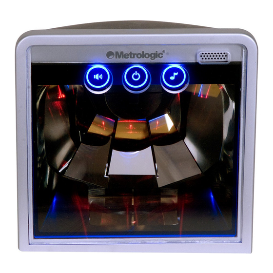
ODEL HARACTERISTICS MS7820 S CANNER Components Figure 1. 7820 Bar Code Scanner Parts Scratch Resistant Output Window (Laser Aperture) Power Save Button Volume Button Blue Indicator LED Speaker Tone Button Cable Connection Area... -
Page 14: Dimensions
ODEL HARACTERISTICS MS7820 S CANNER Dimensions Figure 2. MS7820 Bar Code Scanner Dimensions Connector Panel Figure 3. MS7820 Connector Panel Layout... -
Page 15: Caution And Serial Number Label
ODEL HARACTERISTICS MS7820 S CANNER Caution and Serial Number Labels Figure 4. 7820 Label Location (Top) & Sample Label (Below) Caution To maintain compliance with applicable standards, all circuits connected to the scanner must meet the requirements for SELV (Safety Extra Low Voltage) according to EN/IEC 60950-1. -
Page 16: Installation
NSTALLATION ABLE NSTALLATION NTERFACE PECIFIC Keyboard Wedge Turn off the host system. Disconnect the keyboard from the host. Connect the keyed VLink cable to the 10-pin Multi-Interface jack. It is the only circular keyed jack located on the bottom of the MS7820 (see figure 5). Connect the “Y”... -
Page 17: Usb
NSTALLATION ABLE NSTALLATION NTERFACE PECIFIC Connect the keyed VLink cable to the 10-pin Multi-Interface jack. It is the only circular keyed jack located on the bottom of the MS7820 (see figure 6). Connect the other end of the USB cable to the host. Before continuing, verify the USB cable is connected to the appropriate interface jack on the... -
Page 18: Rs232
NSTALLATION ABLE NSTALLATION NTERFACE PECIFIC RS232 Turn off the host system. Connect the keyed VLink cable to the 10-pin Multi-Interface jack. It is the only circular keyed jack located on the bottom of the MS7820 (see figure 7). Connect the other end of the VLink cable to the host. -
Page 19: Ibm 46Xx
NSTALLATION ABLE NSTALLATION NTERFACE PECIFIC IBM 46xx Turn off the host system. Connect the keyed cable to the 10-pin Multi-Interface jack. It is the only circular keyed jack located on the bottom of the MS7820 (see figure 8). Connect the other end of the cable to the host. -
Page 20: Cable Installation (Secondary Metrologic Scanner)
(AUX) jack, which is located directly next to the circular keyed Multi-Interface jack. The Auxiliary (AUX) jack has a square opening. The following Metrologic scanners can be used in the Auxiliary (AUX) input of the MS7820: the MS9520, MS9540, MS7120, MS7220 or another MS7820. - Page 21 The following bar codes do not apply when using an MS6720 as a secondary scanner. Contact a Metrologic representative for additional information on the MS6720. If the secondary scanner is not a Metrologic scanner refer to Section O of the MetroSelect Configuration Guide. Aux Port Defaults ³...
- Page 22 NSTALLATION ABLE NSTALLATION ECONDARY ETROLOGIC CANNER Figure 9. Connector Orientation (Top) Auxiliary Scanner Setup (Bottom) See SELV Power caution statement located on page 11 of this manual.
-
Page 23: Eas Deactivation
SW1 and SW2 are the switch banks inside the Checkpoint device that set the deactivation range. Metrologic recommends end users program the MS7820 bar code scanner to the Short Range*, so that the unit does not scan out beyond the deactivation range. -
Page 24: Flex Stand Installation, Mlpn 46-00868
NSTALLATION , MLPN 46-00868 TAND NSTALLATION Drill four #39 pilot holes in the counter top for the stand base plate. Figure 11. Base Plate Hole Pattern Attach the flex pole assembly and secure the base plate to the counter. Slide the flex cover over the flex pole assembly. Once the flex pole has been assembled, mount the stand base plate to the counter and install the flex cover over the flex pole assembly. - Page 25 NSTALLATION TAND NSTALLATION Remove the scanner’s back plate from the rear side of the unit. Apply pressure to the points shown in Figure 14 until the back plate unlatches from the scanner. Figure 14. Cable Cover Removal Slide the bottom mounting plate off the scanner. Figure 15.
- Page 26 NSTALLATION TAND NSTALLATION Attach the scanner mounting plate to the flex pole. Figure 16. Secure mounting plate to flex pole. Slide the scanner onto the mounting plate until the plate is fully seated into the scanner. Figure 17. Slide mounting plate into scanner. Before installing the scanner’s cable cover, refer to pages 12-19 for instructions on the proper cable connections.
-
Page 27: Wall Mount Stand Installation, Mlpn 46-00869
NSTALLATION , MLPN 46-00869 OUNT TAND NSTALLATION Locate the area on the wall where the scanner will be mounted and drill four #39 pilot holes in the wall for the stand base plate. Figure 19. Base Plate Hole Pattern Attach the flex pole assembly to the Wall Mount plate. Slide the flex cover over the flex pole assembly. - Page 28 NSTALLATION OUNT TAND NSTALLATION Remove the scanner’s back plate from the rear side of the unit. Apply pressure to the points shown in Figure 21 until the back plate unlatches from the scanner. Figure 21. Cable Cover Removal Slide the bottom mounting plate off the scanner. Figure 22.
- Page 29 NSTALLATION OUNT TAND NSTALLATION Secure the wall mounting plate to the wall location designated in Step 1 and assemble the remaining parts as shown in Figure 23. Figure 23. Scanner Mounting Plate Assembly Slide the scanner onto the mounting plate until the plate is fully seated into the scanner.
- Page 30 NSTALLATION OUNT TAND NSTALLATION Before installing the scanner’s cable cover, refer to pages 12-19 for instructions on the proper cable connections. Re-Install the scanner’s back plate to lock- in the bottom mounting plate. Figure 25. Install back plate...
-
Page 31: Scanner Operation Scan Zone
CANNER PERATION 100% UPC B ASED ON ODES Figure 26. Scan Area Top View (top) Side View (Bottom) Specifications are subject to change without notice. -
Page 32: Depth Of Field By Minimum Bar Code Element Width
CANNER PERATION EPTH OF IELD BY INIMUM LEMENT IDTH 100% UPC B ASED ON ODES Figure 27. Depth of Field Top View Long Range Mode Minimum Bar Code Element Width Long Range Mode .132 .190 .264 .330 .660 mils 10.4 13.0 26.0 Specifications are subject to change without notice. - Page 33 CANNER PERATION EPTH OF IELD BY INIMUM LEMENT IDTH 100% UPC B ASED ON ODES Figure 28. Depth of Field Side View Long Range Mode Minimum Bar Code Element Width Long Range Mode .132 .190 .264 .330 .660 mils 10.4 13.0 26.0 Specifications are subject to change without notice.
- Page 34 CANNER PERATION EPTH OF IELD BY INIMUM LEMENT IDTH 100% UPC B ASED ON ODES Figure 29. Depth of Field Top View Short Range Mode Minimum Bar Code Element Width Short Range Mode .190 .264 .330 10.4 13.0 mils Specifications are subject to change without notice.
- Page 35 CANNER PERATION EPTH OF IELD BY INIMUM LEMENT IDTH 100% UPC B ASED ON ODES Figure 30. Depth of Field Side View Short Range Mode Minimum Bar Code Element Width Short Range Mode .190 .264 .330 mils 10.4 13.0 Specifications are subject to change without notice.
-
Page 36: Indicator Descriptions
CANNER PERATION NDICATOR ESCRIPTIONS Audible When the MS7820 scanner is in operation, it provides audible feedback. These sounds indicate the status of the scanner. Eight settings are available for the tone of the beep (normal, 6 alternate tones and no tone). To change the tone, use the Tone Button or refer to the MetroSelect Configuration Guide. -
Page 37: Visual
CANNER PERATION NDICATOR ESCRIPTIONS Visual There is a blue LED on the top of the MS7820 as well as three illuminated buttons on the front. When the scanner is on, the flashing or constant illumination of the LED indicates the status of the current scan and the scanner. -
Page 38: Failure Modes
CANNER PERATION NDICATOR ESCRIPTIONS Failure Modes Figure 32. LED Flashing BLUE LED and One Razzberry Tone This indicates the scanner has experienced a laser subsystem failure. Return the unit for repair at an authorized service center. Flashing Blue LED and Two Razzberry Tones This indicates the scanner has experienced a motor failure. -
Page 39: Diagnostic Indicator Display
CANNER PERATION NDICATOR ESCRIPTIONS Diagnostic Indicator Display There is a green colored (when illuminated) single digit error code display located to the left of the scanner’s mirrored polygon (see figure to the right). Figure 33. Failure LED RROR ESCRIPTION RAM ERROR – The scanner’s Random Access Memory (RAM) is tested as faulty. -
Page 40: Power Save Modes
CANNER PERATION OWER ODES The MS7820 bar code scanner has five configurable power save modes. Refer to the MetroSelect Configuration Guide for additional information on Power Save Modes. Blink Power Save Mode: “Blinks” the laser OFF & ON after a configured period of non-use. When the scanner recognizes a bar code, it will exit the Blink mode. -
Page 41: Touch Button Panel
CANNER PERATION OUCH UTTON ANEL Figure 34. The Touch Button Panel Operation HANGING THE EEPER Touch the Tone button once and the beeper tone will change. The new tone will be heard. Then two more of the new tones will be heard signifying the new setting has been set. -
Page 42: Maintenance
AINTENANCE EPLACEABLE ROTECTIVE UTER INDOW The MS7820 bar code scanner includes a replaceable protective outer window, which protects the flat-screen window from scratches when used in harsh scanning environments. Figure 39. Figure 38. Replaceable Protective Outer Replaceable Protective Outer Window Easy Removal. Window Easy Installation. -
Page 43: Troubleshooting Guide
ROUBLESHOOTING UIDE The following guide is for reference purposes only. Contact a Metrologic representative at 1-800-ID-METRO or 1-800-436-3876 to preserve the limited warranty terms. MS7820 S ERIES ROUBLESHOOTING UIDE SYMPTOMS POSSIBLE CAUSE(S) SOLUTION All Interfaces Check transformer, outlet and No power is being No LEDs, beep power strip. - Page 44 ROUBLESHOOTING UIDE SYMPTOMS POSSIBLE CAUSE(S) SOLUTION UPC/EAN, Code 39, Interleaved Scanning a particular 2 of 5, Code 93, Code 128 and symbology that is not Codabar are enabled by default. enabled. Verify that the type of bar code being read has been selected. The unit powers up, but does not The scanner has been...
- Page 45 Check if the correct minimum length setting does not symbol length is set. work with the bar code. Multi-Function A faulty push button Contact a Metrologic customer Button is not switch. service representative. working. Keyboard Wedge Only The unit scans...
- Page 46 ROUBLESHOOTING UIDE SYMPTOMS POSSIBLE CAUSE(S) SOLUTION Everything These characters may works except not be supported by Try operating the scanner in Alt for a couple of that country’s key look mode. characters. up table. RS232 Only Increase the intercharacter delay setting.
- Page 47 ROUBLESHOOTING UIDE SYMPTOMS POSSIBLE CAUSE(S) SOLUTION Aux Port Operation with any Interface Trouble with the Refer to the user guide provided secondary with the secondary scanner. scanner. Cable Ensure the secondary scanner is 57-57499x-3] MLPN connected to the MS7820 com may not be connected port marked “Aux”...
-
Page 48: Configuration Modes
• Bar Codes The MS7580 can be configured by scanning the bar codes included in the Metrologic Configuration Guide shipped with the area imager. This manual can also be downloaded FREE from Metrologic’s website (www.metrologic.com). • MetroSet2 This user-friendly Windows-based configuration program allows you to simply ‘point-and-click’... -
Page 49: Upgrading The Firmware
PGRADING THE IRMWARE The MS7820 is part of Metrologic's line of scanners with flash upgradeable firmware. The upgrade process requires, a new firmware file supplied to the customer by a customer service representative and Metrologic's MetroSet2 software . A personal computer running Windows 95 or greater with an available RS232 serial or USB port is required to complete the upgrade. -
Page 50: Scanner And Cable Terminations
CANNER AND ABLE ERMINATIONS CANNER INOUT ONNECTIONS The MS7820 scanner interfaces terminate to 10-pin modular jacks located on the back of the unit. Figure 40. Scanner Interface Ports MS7820 MS7820 EAS Connector Auxiliary Connector Function Function GROUND GROUND ANTENNA + AUX_RxD ANTENNA - AUX_TxD... - Page 51 CANNER AND ABLE ERMINATIONS CANNER INOUT ONNECTIONS Figure 41. Scanner Interface Ports HOST CONNECTOR (Multi-Interface) Function Function RS-232 Keyboard Wedge Ground Ground CTS / DTR Tied to Pin 3 in Cable Data Rx Tied to Pin 2 in Cable PC Data PC Clock RTS* KB Clock...
-
Page 52: Cable Connector Configurations (Host End)
CANNER AND ABLE ERMINATIONS ABLE ONNECTOR ONFIGURATIONS VLink Cable 5S-5Sxxx-3* MLPN Function Shield Ground RS232 Transmit Output RS232 Receive Input Power/Signal Ground Reserved CTS Input † 9-Pin D-Type Conn. RTS Output +5VDC xxx* specifies connection to the host USB Type A, VLink Cable 5S-5S235-3 MLPN Function... - Page 53 PC Clock No Connect Metrologic will supply an adapter cable with a 5-pin DIN male connector on one end and a 6-pin mini DIN female connector on the other. According to the termination required, connect the appropriate end of the adapter cable to the VLink cable, leaving the necessary termination exposed for connecting to the keyboard and the keyboard port on the PC.
-
Page 54: Regulatory Compliance Safety
EGULATORY OMPLIANCE AFETY ITE Equipment IEC 60950-1, EN 60950-1 Laser Laser Class 1: IEC 60825-1:1993+A1+A2, EN 60825-1:1994+A1+A2 Caution Use of controls or adjustments or performance of procedures other than those specified herein may result in hazardous laser light exposure. Under no circumstances should the customer attempt to service the laser scanner. -
Page 55: Emc
EGULATORY OMPLIANCE Emissions FCC Part 15, ICES-003, CISPR 22, EN 55022 Immunity CISPR 24, EN 55024 Changes or modifications not expressly approved by the party responsible for compliance could void the user’s authority to operate the equipment. Class A Devices The following is applicable when the scanner cable is greater in length than 3 meters (9.8 feet) when fully extended: Les instructions ci-dessous s’appliquent aux cables de scanner dépassant 3 métres... -
Page 56: Class B Devices
EGULATORY OMPLIANCE Changes or modifications not expressly approved by the party responsible for compliance could void the user’s authority to operate the equipment. Class B Devices The following is applicable when the scanner cable is less than 3 meters (9.8 feet) in length when fully extended: Les instructions ci-dessous s’appliquent aux cables de scanner ne dépassant pas 3 métres (9.8 pieds) de long en extension maximale: Folgendes trifft zu, wenn das Scannerkabel kürzer als 3 Meter ist:... -
Page 57: Patents
ATENTS This METROLOGIC product may be covered by, but not limited to, one or more of the following U.S. Patents: U.S. Patent No.; 4,960,985; 5,081,342; 5,216,232; 5,557,093; 5,627,359; 5,637,852; 5,661,292; 5,777,315; 5,789,731; 6,029,894; 6,098,885; 6,209,789; 6,347,743; 6,412,696; 6,460,767; 6,975,456 No license right or sublicense is granted, either expressly or by implication,... - Page 58 The MS7820 Solaris™ bar code scanners are manufactured by Metrologic at its Blackwood, New Jersey, U.S.A. facility. The MS7820 Solaris bar code scanners have a two (2) year limited warranty from the date of manufacture. The duration of the warranty is dependent upon the country where the product was purchased.
-
Page 59: Index
NDEX dimensions ........7, 10 AC ............8 accessories ........3, 4 adapter ..........49 EAS .......... 3, 10, 19 audible....... See indicator EMC ........... 51 auxiliary ......3, 43, 47, 48 EMI............. 51 scanner ......16, 17, 18 emissions ........... 51 auxiliary port ........ - Page 60 NDEX repair ..........54 rs232 ......10, 14, 42, 46–49 labels ..........11 laser ........11, 36, 50 laser power........... 7 safety..........50, 52 led ........See indicator scan zone........... 27 limited warranty ........54 secondary scanner... 16, 17, 18, 43 serial label ..........
- Page 62 OTES...
- Page 64 January 2008 Printed in the USA 0 0 - 0 2 2 8 3 B...
Need help?
Do you have a question about the MS7820 Solaris and is the answer not in the manual?
Questions and answers