Table of Contents

Subscribe to Our Youtube Channel
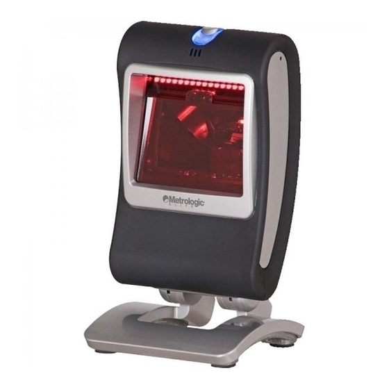
Summary of Contents for Metrologic Genesis MS7580
- Page 1 MS7580 Genesis ™ Supplemental Guide for EAS Equipped Models...
- Page 2 Copyright © 2008 by Metrologic Instruments, Inc. All rights reserved. No part of this work may be reproduced, transmitted, or stored in any form or by any means without prior written consent, except by reviewer, who may quote brief passages in a review, or provided for in the Copyright Act of 1976.
-
Page 3: Table Of Contents
ABLE OF ONTENTS Introduction Document Scope ....................1 Optional Accessories ..................1 Installation Integrated RF EAS Antenna Connection ............2 EAS System Connection................... 3 ® Checkpoint EAS System Integration............3 Configuration Imager Configuration for EAS Applications............4 Operation EAS – Tag Deactivation Range ................ 6 Scanner and Cable Terminations Scanner Pinout Connections ................ -
Page 5: Introduction
NTRODUCTION Document Scope This guide provides additional information required for the installation, configuration, and operation of MS7580 models equipped with EAS (MS7580-118-EAS). This guide is intended to be used in conjunction with the standard MS7580 Genesis, Presentation Area-Imager, Installation and User’s Guide (PN 00-02290). -
Page 6: Installation
Figure 2. Slide the tab (C) on the cover into the space between the box receptacle and the stand (see Figure 3 Install the socket screw (D) to secure the cover to the stand (see Figure 3 Figure 3. www.metrologic.com... -
Page 7: Eas System Connection
EAS system. ® Checkpoint EAS System Integration Metrologic cables compatible with Checkpoint EAS systems include five additional wires for device connection. Consult the table below for the appropriate wire and terminal configuration. † Antenna and Interlock... -
Page 8: Configuration
In continuous mode, the imager will signal the EAS system to activate when it first powers on. The area imager will never ³ deactivate the EAS system while in continuous mode. The EAS timeout setting has no effect in continuous mode. www.metrologic.com... - Page 9 ONFIGURATION Scan the desired EAS timeout length (applicable for regular mode only). The EAS timeout length specifies the maximum time that the area imager will leave the EAS interlock signal asserted following a successful scan. If the area imager commonly fails to deactivate EAS tags, try increasing the value of the timeout setting.
-
Page 10: Operation
MS7580. Proper tag deactivation requires the entire tag to pass through the expected tag deactivation range indicated in figures 4 and 5. Figure 4. Expected Tag Deactivation Area (Side View) Specifications are subject to change without notice. www.metrologic.com... - Page 11 PERATION Figure 5. Expected Tag Deactivation Area (Top View) Specifications are subject to change without notice.
-
Page 12: Scanner And Cable Terminations
Signal/Power Ground SHELL SHELL 2-Pin Box Receptacle Function EAS ANT - Figure 7. EAS ANT + USB requires 12V power for pass-through functionality. Signals on Pin 6 and 8 are TTL full level RS232 output signals on MS7580-118-EAS models. www.metrologic.com... -
Page 13: Cable Connector Configurations
CANNER AND ABLE ERMINATIONS Cable Connector Configurations (Host End of Cable) RS232, 12V VLink Cable MX-5S000-E-3 Function Shield Ground RS232 Transmit Output RS232 Receive Input No Connect Power/Signal Ground CTS Input Figure 8. 9-Pin Female, D-Type RTS Output Host +12VDC MX-5S235-E-3 Function PC +5V/V_USB... -
Page 14: Limited Warranty
This limited warranty does not extend to any Product which in the sole judgment of Metrologic, has been subjected to abuse, misuse, neglect, improper installation, or accident, nor any damage due to use or misuse produced from integration of the Product into any mechanical, electrical or computer system. - Page 16 00-05269A November 2008, Printed in China © 2008 Metrologic Instruments, Inc.


Need help?
Do you have a question about the Genesis MS7580 and is the answer not in the manual?
Questions and answers