
Related Manuals for Metrologic MS7320 InVista Series


Summary of Contents for Metrologic MS7320 InVista Series
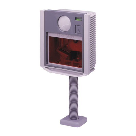
- Page 1 METROLOGIC INSTRUMENTS, INC. ™ MS7320 InVista Series Installation and User’s Guide...
- Page 3 Copyright © 2002 by Metrologic Instruments, Inc. All rights reserved. No part of this work may be reproduced, transmitted, or stored in any form or by any means without prior written consent, except by reviewer, who may quote brief passages in a review, or provided for in the Copyright Act of 1976.
-
Page 4: Table Of Contents
ABLE OF ONTENTS Introduction......................1 Scanner and Accessories..................2 Installation for OCIA Interface ................4 Installation for Keyboard Wedge Interface ............5 Installation for Stand-Alone Keyboard Interface ...........6 Installation for USB Interface................7 Installation for RS232 or Light Pen Interfaces ............8 Installation for IBM 46xx Interface ..............10 Installation of an Auxiliary Scanner..............11 Scanner Parts .....................14 Maintenance .......................14... -
Page 5: Introduction
NTRODUCTION ™ The MS7320 InVista offers an outstanding combination of features, versatility, performance, and durability. This fixed mount laser bar code scanner provides ease of use and high throughput speeds by featuring a large, dynamic, and aggressive scan volume. The MS7320 is equipped with a multitude of standard features including: •... -
Page 6: Scanner And Accessories
Keyboard Wedge PowerLink Cable with Adapter Cable Metrologic Voltage Converter Cable, MVC** +12VDC to +5.2VDC or -12VDC to +5VDC Contact a Metrologic Customer Service representative for additional information on Metrologic’s MVC cable series and the host connections available. 54-54020 Stand Alone Keyboard Wedge PowerLink Cable 54-54165... - Page 7 Description 46-46624 Everscan Window Face Plate 46-46625 Standard Window Face Plate Other items may be ordered for the specific protocol being used. To order additional items, contact the dealer, distributor or call Metrologic’s Customer Service Department at 1-800-ID-METRO or 1-800-436-3876.
-
Page 8: Installation For Ocia Interface
OCIA I NSTALLATION FOR NTERFACE Turn off the host system. Connect the MVC cable to the 10-pin OCIA interface jack. It is the 2 round opening from the left side of the MS7320 (see figure 1). Connect the other end of the MVC cable to the host. -
Page 9: Installation For Keyboard Wedge Interface
NSTALLATION FOR EYBOARD EDGE NTERFACE Turn off the host system. Disconnect the keyboard from the host. Connect the PowerLink cable to the 10-pin KBW interface jack. It is the 2 round opening from the left side of the MS7320 (see figure 2). Connect the “Y”... -
Page 10: Installation For Stand-Alone Keyboard Interface
NSTALLATION FOR TAND LONE EYBOARD NTERFACE Turn off the host system. Disconnect the keyboard from the host. Connect the PowerLink cable to the 10-pin Stand-Alone Keyboard interface jack. It is the 2 round opening from the left side of the MS7320 (see figure 3). Connect the other end of the PowerLink cable to the keyboard port on the host. -
Page 11: Installation For Usb Interface
USB I NSTALLATION FOR NTERFACE Turn off the host system. Determine if your application requires USB Keyboard communication protocols or USB Point-of-Sale communication protocols. If you require USB Keyboard communication protocols, skip to step 4. If you require USB Point-of-Sale communication protocols set the dip Figure 4a: POS Dip Switch switches shown in figure 4a to positions... -
Page 12: Installation For Rs232 Or Light Pen Interfaces
RS232 NSTALLATION FOR IGHT NTERFACES Turn off the host system. Connect the PowerLink cable to the 10-pin RS232/Light Pen interface jack. It is the 1 round opening from the left side of the MS7320 (see figure 5). Connect the other end of the PowerLink cable to the host. - Page 13 RS232 NSTALLATION FOR IGHT NTERFACES Codes needed for Step 7 on page 8. For RS232 Communication: Recall Defaults Scan 1 ³ Enable RS-232 Scan 2 ³ For Light Pen Communication: Recall Defaults Scan 1 ³ Enable Light Pen/Wand Scan 2 ³...
-
Page 14: Installation For Ibm 46Xx Interface
IBM 46 NSTALLATION FOR NTERFACE Turn off the host system. Connect the MVC cable to the 10-pin IBM 46xx interface jack. It is the round opening from the left side of the MS7320 (see figure 6). Connect the other end of the MVC cable to the host. -
Page 15: Installation Of An Auxiliary Scanner
MS7320. The Aux jack has a square opening. The following Metrologic scanners can be used in the “Aux” input of the MS7320: the MS9520, MS9540, MS6220, MS7120, MS6520, MS6720, MS7220 or another MS7320. - Page 16 MS6720, to be used as an auxiliary scanner. Contact a Metrologic representative for additional information on the MS6720. Reserve Code 32 ³ Metrologic recommends disabling the beeper on the auxiliary scanner. Refer to ‘Beeper Options’ in the Communications section of the MetroSelect Configuration Guide ( 00-02407A-1 & -2).
- Page 17 NSTALLATION OF AN UXILIARY CANNER Figure 7: Connector Orientation (Top) Auxiliary Scanner Setup (Bottom)
-
Page 18: Scanner Parts
CANNER ARTS Figure 8: Scanner Parts Output Window (Laser Aperture) Speaker (Under the Window Cover) Replaceable Window Face Plate Red LED (Top LED) Green LED (Bottom LED) Muli-Function Button (see page 20) Cable Connection and Dip Switch Area Cable Cover Stand Foot AINTENANCE Smudges and dirt can interfere with the proper scanning of a bar code. -
Page 19: Cable Cover Installation And Removal
ABLE OVER NSTALLATION AND EMOVAL Figure 9: Installing the Cable Cover (left). Removing the Cable Cover (bottom right). LATE EMOVAL Figure 10: Face Plate Removal... -
Page 20: Scanner Labels
CANNER ABELS The MS7320 has 2 labels on the back of the unit. These labels contain the model number, date of manufacture, serial number, and caution information. An additional caution label is located under the window faceplate and a label noting the jack interfaces is located under the connector cover. -
Page 21: Audible Indicators
UDIBLE NDICATORS When the MS7320 scanner is in operation, it provides audible feedback. These sounds indicate the status of the scanner. Eight settings are available for the tone of the beep (normal, 6 alternate tones and no tone). To change the tone, ®... -
Page 22: Visual Indicators
ISUAL NDICATORS There is a red LED and green LED on the front of the MS7320. When the scanner is on, the flashing or constant illumination of the LEDs indicates the status of the current scan and the scanner. Figure 12: LEDs No Red or Green LED The LEDs will not be illuminated if the scanner is not receiving power from the host or transformer. -
Page 23: Failure Modes
AILURE ODES Figure 13: LEDs Flashing Green and One Razzberry Tone This indicates the scanner has experienced a laser subsystem failure. Return the unit for repair at an authorized service center. Flashing Red and Green and Two Razzberry Tones This indicates the scanner has experienced a motor failure. Return the unit for repair at an authorized service center. -
Page 24: Power Save Modes And The Multi-Function Button
OWER ODES AND THE ULTI UNCTION UTTON The MS7320 has five programmable power save modes. Refer to the MetroSelect Programming Guide for additional information on Power Save Modes. Blink Power Save Mode (Default): “Blinks” the laser OFF & ON after a programmed period of non-use. When the scanner recognizes a bar code it will exit the Blink mode. - Page 25 OWER ODES AND THE ULTI UNCTION UTTON Figure 14: The Multi-Function Button HANGING THE EEPER hort (<3 second) depression and the beeper tone will change. The new tone will be heard, followed by a short pause. Then two more of the new tones will be heard signifying the new setting has been stored in memory.
-
Page 26: Scan Volume
OLUME 100% UPC B ASED ON ODES Figure 18: Scan Area Top View (top) Side View (Bottom) Specifications subject to change without notice. -
Page 27: Depth Of Field By Minimum Bar Code Element Width
EPTH OF IELD BY INIMUM LEMENT IDTH 100% UPC B ASED ON ODES Figure 19: Depth of Field Top View M inimum Bar Code Element Width 10.4 mils Specifications subject to change without notice. - Page 28 EPTH OF IELD BY INIMUM LEMENT IDTH 100% UPC B ASED ON ODES Figure 20: Depth of Field Side View M inimum Bar Code Element Width 10.4 mils Specifications subject to change without notice.
-
Page 29: Flex Stand Installation
TAND NSTALLATION The Optional Flex Stand ( 45-45483) includes: MLPN a. Shoe Mount ........Qty. 1 b. Stand Base Cover ......Qty. 1 c. Stand Base........Qty. 1 d. Small Flex Cover ......Qty. 1 e. Flex Pole ........Qty. 1 f. Large Flex Cover......Qty. 1 g. - Page 30 TAND NSTALLATION CONTINUED Optional Flex Stand ( 45-45483) installation continued from page 25. MLPN Figure 25 Figure 26...
-
Page 31: Eas Deactivation Antenna
NTENNA SW1 and SW2 are the switch banks inside the Checkpoint Device that set the deactivation range. Metrologic recommends end users program the MS7320 to the Fixed Low-Density depth of field, so that the unit does not scan out beyond the deactivation range. -
Page 32: Troubleshooting Guide
ROUBLESHOOTING UIDE The following guide is for reference purposes only. Contact a Metrologic representative at 1-800-ID-METRO or 1-800-436-3876 to preserve the limited warranty terms. MS7320 S ERIES ROUBLESHOOTING UIDE SYMPTOMS POSSIBLE CAUSE(S) SOLUTION All Interfaces Check transformer, outlet and No power is being No LEDs, beep power strip. - Page 33 ROUBLESHOOTING UIDE ONTINUED SYMPTOMS POSSIBLE CAUSE(S) SOLUTION UPC/EAN, Code 39, interleaved Scanning a particular 2 of 5, Code 93, Code 128 and symbology that is not Codabar are enabled by default. enabled. Verify that the type of bar code being read has been selected. The unit powers up, but does The scanner has been...
- Page 34 Multi-Function compressing fully. freely. Button is not working. A faulty push button Contact a Metrologic Customer switch. Service Representative. Keyboard Wedge Only The unit scans Make sure the scanner is Configuration is not the bar code but configured for the appropriate correct.
- Page 35 ROUBLESHOOTING UIDE ONTINUED SYMPTOMS POSSIBLE CAUSE(S) SOLUTION Everything These characters may works except not be supported by Try operating the scanner in Alt for a couple of that country’s key look mode. characters. up table. RS-232 Only Increase the interscan code The unit is delay setting.
- Page 36 Disconnect then reconnect the The scanner USB cable at the host end. emits a razz tone Contact a Metrologic and the LEDS The USB port is not flash three times operating correctly. Representative if symptoms when configured persist.
-
Page 37: Design Specifications
Scan Lines: Min Bar Width: 0.127 mm (5.0 mil) Autodiscriminates all standard bar codes; for other Decode Capability: symbologies call Metrologic PC Keyboard Wedge, RS-232, OCIA, Light Pen, System Interfaces: Stand Alone PC Keyboard, USB, IBM 468x/469x Print Contrast: 35% minimum reflectance difference No. - Page 38 ESIGN PECIFICATIONS ONTINUED MS7320 S ERIES ESIGN PECIFICATIONS LECTRICAL Input Voltage: 5.2VDC ± 0.25V Power: 1.9 W Operating Current: 360 mA DC Transformers: Class II; 5.2 VDC @ 650 mA Class 1 Laser Product: IEC 60825-1:1993+A1:1997+A2:2001 EMC: FCC, ICES-003 & EN 55022 Class B NVIRONMENTAL Operating Temperature: 0°C to 40°C (32°F to 104°F)
-
Page 39: Rs232 Demonstration Program
RS232 D EMONSTRATION ROGRAM If an RS232 scanner is not communicating with your IBM compatible PC, key in the following BASIC program to test that the communication port and scanner are working. This program is for demonstration purposes only. It is only intended to prove that cabling is correct, the com port is working, and the scanner is working. -
Page 40: Applications And Protocols
The MS7320 with Built-in PC Keyboard Wedge Interface is designed to be used for keyboard emulation only. Many RS-232 programmable functions available in other Metrologic scanners are also available as keyboard wedge functions. The following are the most important selectable options specific to the keyboard wedge. -
Page 41: Default Settings
EFAULT ETTINGS Many functions of the scanner can be "programmed" - that is, enabled or disabled. The scanner is shipped from the factory programmed to a set of default conditions. The default parameter of the scanner has an asterisk ( * ) in the charts on the following pages. If an asterisk is not in the default column then the default setting is Off or Disabled. - Page 42 EFAULT ETTINGS ONTINUED Light Parameter Default OCIA RS-232 46XX Spaces High as Code 39 Bars High as Scanned Spaces High as Scanned DTS/SIEMENS DTS/NIXDORF NCR F NCR S Poll Light Pen Source Beeper Tone Normal Before Beep/Transmit Sequence Transmit Beeper Volume Loudest Communication Timeout None...
- Page 43 EFAULT ETTINGS ONTINUED Light Parameter Default OCIA RS-232 46XX Same Symbol Rescan Timeout: 2000 msecs Intercharacter Delay 1 msecs Programmable in 1 msec 10 msecs in steps (MAX 255 msecs) Number of Scan Buffers Transmit EAN-8 Check Digit Transmit EAN-13 Check Digit Transmit UPC-A Check Digit Transmit UPC-E Check Digit Expand UPC-E...
- Page 44 EFAULT ETTINGS ONTINUED Light Parameter Default OCIA RS-232 46XX 8 Data Bits 7 Data Bits Transmit Sanyo ID Characters Nixdorf ID LRC Enabled UPC Prefix UPC Suffix Transmit AIM ID Characters STX Prefix ETX Suffix Carriage Return Line Feed - disabled by default in KBW Tab Prefix Tab Suffix...
- Page 45 EFAULT ETTINGS ONTINUED Light Parameter Default OCIA RS-232 46XX Bookland 977 (2 digit) Supplemental Requirement Supplements are not Required Two Digit Redundancy Five Digit Redundancy 100 msec to Find Supplement Programmable in 100 msec steps (MAX 800 msec) as code Coupon Code 128 Programmable Code Lengths 7 avail.
- Page 46 EFAULT ETTINGS ONTINUED Default settings for “Aux” interface The slave scanner and the MS7320 always communicate via RS232. Data is relayed to the host via various primary interfaces. Light Parameter Default OCIA RS-232 46XX Aux Baud Rate 38400 Aux parity space Aux data bits Aux stop bits...
-
Page 47: Scanner And Cable Terminations
CANNER AND ABLE ERMINATIONS Scanner Pinout Connections The MS7320 scanner interfaces terminate to 10-pin modular jacks located on the back of the unit. The serial # label indicates the model number of the scanner. Figure 28: Scanner Interface Ports MS732x-13 OCIA MS732x-13 IBM 46xx Function Function... - Page 48 CANNER AND ABLE ERMINATIONS ONTINUED Figure 29: Scanner Interface Ports MS732x-37 MS732x-37 Keyboard Wedge, Stand RS-232 or Light Pen Alone-Keyboard or USB Function Function Ground Ground USB D- RS-232 Transmit Output USB D+ RS-232 Receive Input PC Data RTS Output PC Clock CTS Input KB Clock...
- Page 49 CANNER AND ABLE ERMINATIONS ONTINUED Cable Connector Configurations (Host End) PowerLink Cable 54-54xxx* MLPN Function Shield Ground RS-232 Transmit Output RS-232 Receive Input DTR Input Power/Signal Ground Reserved CTS Input 9-Pin D-Type Conn. RTS Output +5VDC xxx* specifies connection to the host USB PowerLink Cable 54-54165, Type A) MLPN...
- Page 50 6-pin mini DIN male on the other. PowerLink Cable 5-Pin DIN, Female 6-Pin DIN, Male Metrologic will supply an adapter cable with a 5-pin DIN male connector on one end and a 6-pin mini DIN female connector on the other. Adapter Cable 5-Pin Din, Male...
-
Page 51: Limited Warranty
In the event that it is determined the equipment failure is covered under this warranty, Metrologic shall, at its sole option, repair the Product or replace the Product with a functionally equivalent unit and return such repaired or replaced Product without charge for service or return freight, whether distributor, dealer/reseller, or retail consumer, or refund an amount equal to the original purchase price. -
Page 52: Notices
OTICES This device complies with Part 15 of the FCC Rules. Operation is subject to the following two conditions: (1) This device may not cause harmful interference, and (2) this device must accept any interference received, including interference that may cause undesired operation. This equipment has been tested and found to comply with the limits for a Class B digital device, pursuant to Part 15 of the FCC rules. - Page 53 OTICES ONTINUED Caution Use of controls or adjustments or performance of procedures other than those specified herein may result in hazardous laser light exposure. Under no circumstances should the customer attempt to service the laser scanner. Never attempt to look at the laser beam, even if the scanner appears to be nonfunctional.
-
Page 54: Patents
ATENTS “Patent Information This METROLOGIC product may be covered by one or more of the following U.S. Patents: U.S. Patent No.; 4,960,985; 5,081,342; 5,216,232; 5,557,093; 5,627,359; 5,637,852; 5,661,292; 5,777,315; 5,789,731; 6,029,894; 6,098,885; 6,209,789; 4,360,798; 4,369,361; 4,387,297; 4,460,120; 4,496,831; 4,593,186; 4,607,156; 4,673,805; 4,736,095; 4,758,717; 4,816,660; 4,845,350;... -
Page 55: Index
NDEX Keyboard Type ......36 Accessories ........2 Keyboard Wedge 1, 2, 5, 33, 36, 44 Adapter ........46 Audible.........17 Autodiscriminates ......33 Labels.......... 16 LED ....14, 17, 18, 28, 29, 33 Light Levels ......... 34 Bar Code ......22, 23, 24 Light Pen ..1, 8-10, 33, 36-42, 44 Beep ........17, 38 Light Source ........ - Page 56 NDEX Specifications .... 22-24, 33, 34 Stand .......25, 26, 33 Ventilation ........34 Storage ........34 Visual .......... 18 System Interfaces......33 Voltage ....4, 5, 6, 7, 8, 10, 11 Termination........33 Warranty ........47 Transformers .......34 Weight......... 33 Troubleshooting...28, 29, 30, 31, 32 Window Cover......
- Page 57 OTES...
- Page 58 OTES...
- Page 60 April 2002 Printed in the USA 0 0 - 0 2 8 9 6 A...
Need help?
Do you have a question about the MS7320 InVista Series and is the answer not in the manual?
Questions and answers