Table of Contents
Advertisement
Quick Links
Advertisement
Table of Contents

Related Manuals for Rohde & Schwarz FE50DTR


Summary of Contents for Rohde & Schwarz FE50DTR
- Page 1 ® R&S FE50DTR External Frontend Manual (;ÝOÞ2) 1179318002 Version 02...
- Page 2 ® This manual describes the following R&S FE50DTR model and its option: ● FE50DTR, variant K2: 50 GHz up-/down-converter (1347.4099K02) © 2021 Rohde & Schwarz GmbH & Co. KG Mühldorfstr. 15, 81671 München, Germany Phone: +49 89 41 29 - 0 Email: info@rohde-schwarz.com...
-
Page 3: Table Of Contents
4 Preparing for use..............12 4.1 Lifting and carrying................12 4.2 Unpacking and checking..............12 4.3 Choosing the operating site.............. 12 4.4 Setting up the R&S FE50DTR............13 4.5 Considerations for test setup............14 4.6 Connecting to power................15 4.7 Connecting to LAN................16 4.8 Connecting to SMA and 1.85 mm............ - Page 4 5.3 Electronic label................... 25 6 Operating the instrument............27 6.1 Operating the R&S FE50DTR in Rx mode.........27 6.2 Operating the R&S FE50DTR in Tx mode......... 31 6.3 Operating the R&S FE50DTR in simultaneous mode...... 35 6.4 Performing other operational tasks and troubleshooting....39 7 Transporting.................40...
-
Page 5: Safety And Regulatory Information
® Safety and regulatory information R&S FE50DTR Safety Instructions Safety and regulatory information The product documentation helps you use the product safely and efficiently. Fol- low the instructions provided here and in the following chapters. Intended use The product is intended for the development, production and verification of elec- tronic components and devices in industrial, administrative, and laboratory envi- ronments. - Page 6 ® Safety and regulatory information R&S FE50DTR Safety Instructions Never open the casing of the product. Only service personnel authorized by Rohde & Schwarz are allowed to repair the product. If any part of the product is damaged or broken, stop using the product. Contact Rohde & Schwarz customer service at http://www.customersupport.rohde-schwarz.com.
- Page 7 ® Safety and regulatory information R&S FE50DTR Safety Instructions Connecting to power The product is an overvoltage category II product. Connect the product to a fixed installation used to supply energy-consuming equipment such as household appliances and similar loads. Keep in mind that electrically powered products have risks, such as electric shock, fire, personal injury or even death.
-
Page 8: Labels On R&S Fe50Dtr
● Identification and network information, see Electronic label, page 25 Table 1-1: Labels regarding R&S FE50DTR and environment safety Labeling in line with EN 50419 for disposal of electrical and electronic equipment after the product has come to the end of its service life. For more information, see "Dispos-... -
Page 9: Korea Certification Class A
® Safety and regulatory information R&S FE50DTR Korea certification class A NOTICE Potential risks of damage. Could result in damage to the supported product or to other property. Korea certification class A 이 기기는 업무용(A급) 전자파 적합기기로서 판매자 또는 사용자는 이 점을 주의하... -
Page 10: Documentation Overview
It also provides information on maintenance, storage and dis- posal. A printed version is delivered with the product. For information on how to configure and use the R&S FE50DTR in setups with a Rohde & Schwarz vector signal generator and Rohde & Schwarz vector signal analyzer, see the user manual of these instruments. -
Page 11: Key Features
® Key features R&S FE50DTR Key features The R&S FE50DTR External Frontend features: ● Frequency up- and down-conversion, e.g., for 5G NR mmWave testing ● mmWave frequencies from 36 GHz to 50 GHz ● RF connectors with: – Specified output power (PEP) of -30 dBm to 0 dBm –... -
Page 12: Preparing For Use
Preparing for use Here, you can find basic information about setting up the product for the first time. Lifting and carrying Carry the R&S FE50DTR with the top of the external frontend facing upwards. "Lifting and carrying the product" on page 6. -
Page 13: Setting Up The R&S Fe50Dtr
For testing, you can place the R&S FE50DTR on a bench top. 1. Place the R&S FE50DTR on a stable, flat and level surface. Ensure that the surface can support the weight of the R&S FE50DTR. For information on the weight, see the data sheet. -
Page 14: Considerations For Test Setup
Prevent overheating as follows: ● Keep a minimum distance of 3 cm between the fan openings at the front panel and at the rear panel of the R&S FE50DTR and any object in the vicinity. ● Do not place the R&S FE50DTR next to heat-generating equipment such as radiators or other instruments. -
Page 15: Connecting To Power
Connecting to power For safety information, see "Connecting to power" on page 7. For information on the external power supply, see the data sheet. The power supply connector is located on the rear panel of the R&S FE50DTR. Manual 1179.3180.02 ─ 02... -
Page 16: Connecting To Lan
► Connect the DC power cable to the socket of the power supply connector. Only use the DC power cable delivered with the R&S FE50DTR. If connected to power, the R&S FE50DTR is switched-on automatically. On the front panel of the R&S FE50DTR, the "Power" LED switches from gray to green. Table 4-1 provides an overview on power states. -
Page 17: Connecting To Sma And 1.85 Mm
IP address via the Auto-IP/Zeroconf (APIPA) protocol. LAN connection states On the front panel of the R&S FE50DTR, the LAN LED indicates the LAN connec- tion state. The table below provides an overview. Table 4-2: Overview LAN connection states... -
Page 18: Connecting The R&S Fe50Dtr
3. NOTICE! Risk of instrument damage. You can damage the R&S FE50DTR, when you exceed maximum input levels and voltages of the connectors. Set an input level at the connectors of the R&S FE50DTR within the range as given in the data sheet. - Page 19 Tx (transmit) mode and Rx (receive) mode. For detailed information on how the R&S FE50DTR is used in test setups and the connections for each operation mode, see Chapter 6, "Operating the instrument",...
-
Page 20: Switching On Or Off
The R&S FE50DTR is switched off, but connected to power. The "Power" LED is gray. See Table 4-1. ► On the rear panel of the R&S FE50DTR, press the "Power" key . See Chap- ter 5.2.8, "Power key", on page 25. -
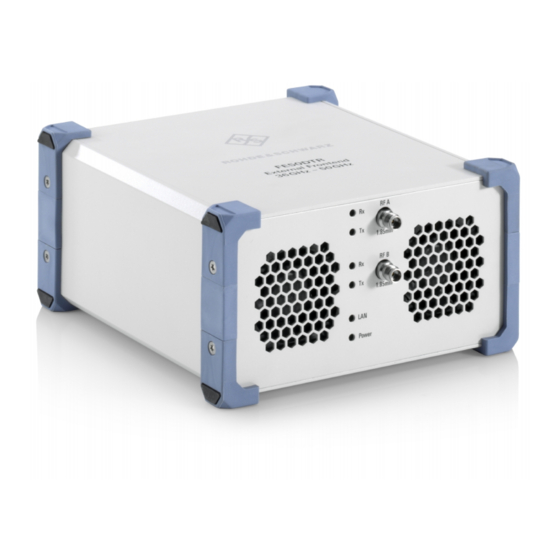
Page 21: Instrument Tour
25. Front panel tour This section gives an overview of the front panel elements of the R&S FE50DTR. The maximum input levels and voltages of the connectors on the front panel must not be exceeded, see "Signal input and output levels"... - Page 22 ® Instrument tour R&S FE50DTR Front panel tour 5.1.1 RF connectors Two bi-directional 1.85 mm female connectors "RF A"/"RF B" for input and output of RF signals. RF signals have a frequency range of 36 GHz to 50 GHz. ● "RF A": Input of the RF signal from the DUT. This signal is down-converted to the frequency, which is measurable for the vector signal analyzer, e.g.,...
-
Page 23: Rear Panel Tour
R&S FE50DTR Rear panel tour Rear panel tour This section gives an overview of the rear panel elements of the R&S FE50DTR. Figure 5-2: R&S FE50DTR rear panel IF connectors, page 23 Ref. In connector, page 24 LO in/LO out connectors, page 24... - Page 24 Chapter 4.6, "Connecting to power", on page 15 5.2.6 LAN connector RJ-45 connector to connect the R&S FE50DTR to a LAN. Connection is required to control the R&S FE50DTR by a vector signal generator and/or a vector signal analyzer. Manual 1179.3180.02 ─ 02...
-
Page 25: Electronic Label
5.2.7 IP preset key Key to preset IP address of the R&S FE50DTR. 5.2.8 Power key Power key to switch on and switch off the R&S FE50DTR. How to: Chapter 4.10, "Switching on or off", on page 20 Electronic label This section explains the electronic label and its elements, which are located on the right side panel of the frontend casing. - Page 26 ® Instrument tour R&S FE50DTR Electronic label Label Label element Description Subnet Displays the bit group of the subnet in the host identifier. Gateway Displays the gateway address. This address identifies the router that is used to forward traffic to destinations beyond the local network.
-
Page 27: Operating The Instrument
(DUT). It downconverts this signal using its own internal local oscillator to an intermediate frequency (IF) signal that is a low-frequency signal. The R&S FE50DTR outputs and transmits the IF signal to the vector signal ana- lyzer. - Page 28 R&S FSV/A locks the R&S FE50DTR to control the R&S FE50DTR exclusively. 1. Check, that no other instrument controls the R&S FE50DTR. The LAN LED on the front panel of the R&S FE50DTR must be green, see "LAN connection states"...
- Page 29 7. Set the "Connection State" to "On". It can take up to 10 seconds until the R&S FSV/A sets up the control connec- tion to the R&S FE50DTR. The displayed status of the control connection switches from "Not Connected" (white) to "Connected" (green).
- Page 30 R&S FE50DTR. Configure this setting in the "Frontend Config" dialog of R&S FSV/A. 1. To define IF range and internal LO of the R&S FE50DTR, set the "Frequency Band Config" mode: ● "IF High": A higher IF is used on the external frontend, resulting in a higher IF input frequency at the R&S FSV/A.
-
Page 31: Operating The R&S Fe50Dtr In Tx Mode
Operating the R&S FE50DTR in Tx mode In Tx mode, the R&S FE50DTR receives a low-frequency IF signal from the vec- tor signal generator. It upconverts this signal using its own internal local oscillator (LO) to a high-frequency RF signal. - Page 32 To connect the R&S FE50DTR for Tx mode The R&S FE50DTR is connected to power switched ► Connect all connectors for connections between the R&S FE50DTR and R&S SMW, and R&S FE50DTR (RF Out) and DUT as in Table 6-2.
- Page 33 Operating the R&S FE50DTR in Tx mode To control the R&S FE50DTR with a vector signal generator The R&S SMW controls the R&S FE50DTR using a secure socket layer (SSL) control connection via LAN. The following step-by-step description explains how the R&S SMW locks the R&S FE50DTR to control the R&S FE50DTR exclusively.
- Page 34 R&S FE50DTR switches from green to orange. If you change the network configuration, e.g. the IP address, the connection to the R&S FE50DTR is aborted. You must re-establish a connection to the frontend as in step 3). If you have connection issues, see section „Troubleshooting External Frontend Control“...
-
Page 35: Operating The R&S Fe50Dtr In Simultaneous Mode
R&S FE50DTR. Configure this setting in the "RF Frontend" dialog of the R&S SMW. 1. To define IF range and internal LO of the R&S FE50DTR, set the "Frequency Band Config" mode: ● "IF High": Requires an R&S SMW equipped with frequency option R&S SMW-B1007 or higher. - Page 36 FE50DTR Operating the R&S FE50DTR in simultaneous mode lator (LO) to a high-frequency RF signal. The R&S FE50DTR outputs and trans- mits this RF signal to the DUT. The DUT processes the signal and responds with a high-frequency RF signal that the R&S FE50DTR receives.
- Page 37 (SSL) control connection via LAN. For correct opera- tion, the R&S FE50DTR operates in Tx mode first and requires control by the R&S SMW. For analysis, the R&S FE50DTR also operates in Rx mode and requires control by the R&S FSV/A.
- Page 38 R&S FE50DTR, reestablish the control connection between R&S FSV/A and R&S FE50DTR ("Connection State" > "On"). To configure frequency settings Simultaneous mode operation of the R&S FE50DTR requires an identical setting of the frequency band configuration at the R&S SMW and at the R&S FSV/A. How to: ●...
-
Page 39: Performing Other Operational Tasks And Troubleshooting
R&S FSV(A)3030 R&S FSV(A)3044 Performing other operational tasks and trouble- shooting Other operational tasks with the R&S FE50DTR include: ● Correcting IF cable losses ● Calibrating the external frontend ● Checking and updating the firmware of the external frontend For a description of these tasks, see the documentation of the control instrument: ●... -
Page 40: Transporting
Securing When moving the R&S FE50DTR in a vehicle or using transporting equipment, make sure that the R&S FE50DTR is properly secured. Only use items intended for securing objects. Transport altitude Unless otherwise specified in the data sheet, the maximum transport altitude with- out pressure compensation is 4500 m above sea level. -
Page 41: Maintenance, Storage And Disposal
® Maintenance, storage and disposal R&S FE50DTR Disposal Maintenance, storage and disposal The product does not require regular maintenance. It only requires occasional cleaning. It is however advisable to check the nominal data from time to time. Cleaning Use a dry, lint-free cloth to clean the product. When cleaning, keep in mind that the casing is not waterproof. - Page 42 ® Maintenance, storage and disposal R&S FE50DTR Disposal fulfills its obligation to take back and dispose of electrical and electronic waste. Contact your local service representative to dispose of the product. Manual 1179.3180.02 ─ 02...
-
Page 43: Contacting Customer Support
® Contacting customer support R&S FE50DTR Contacting customer support Technical support – where and when you need it For quick, expert help with any Rohde & Schwarz product, contact our customer support center. A team of highly qualified engineers provides support and works with you to find a solution to your query on any aspect of the operation, program- ming or applications of Rohde &... -
Page 44: Glossary: Abbreviations And Definitions
Glossary: Abbreviations and definitions R&S FE50DTR Glossary: Abbreviations and definitions DTR: Dual transmit receive Refers to simultaneous operation of the R&S FE50DTR DUT: Device under test FE: Frontend mmWave: Millimeter wave OTA: Over the air PEP: Peak envelope power Rx: Receive mode Tx: Transmit mode Manual 1179.3180.02 ─... -
Page 45: Index
IP preset ..........25 To REF ..........17 Power ..........25 To RF ..........17 Key features ..........11 To SMA ..........17 Connecting the R&S FE50DTR ....18 Connector IF In B ..........23 Connecting ..........16 IF Out A ..........23 Environment ........16 LAN ............. - Page 46 ® Index R&S FE50DTR Overview ..........23 Power key ........... 25 Power supply connector ..... 24 Ref. In connector ........ 24 USB In connector ........24 Regulatory information ......5 Safety ............5 Warning messages ....... 8 Safety information ........5 Safety instructions .......
Need help?
Do you have a question about the FE50DTR and is the answer not in the manual?
Questions and answers