Life Fitness CLUB Series Assembly Instructions Manual
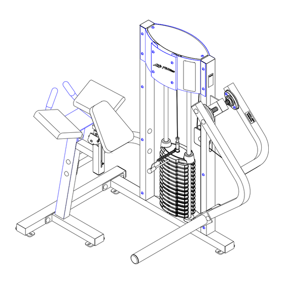
Glute machine
Hide thumbs
Also See for CLUB Series:
- User manual (48 pages) ,
- Service manual (35 pages) ,
- Operation manual (26 pages)

Related Manuals for Life Fitness CLUB Series


Summary of Contents for Life Fitness CLUB Series
-
Page 1: Assembly Instructions
CLUB SERIES GLUTE MACHINE ASSEMBLY INSTRUCTIONS Part # 7109801 Revision:11/12/01 Rev D. -
Page 2: Parts List
PARTS LIST PART # DESCRIPTION PART # DESCRIPTION 71086xx TOWER 3102901 3/8 X 1-1/4” BOLT 7113101 CABLE 3102933 3/8 X 2” BOLT 6793001 LABE, PRODUCT WARNING 2" 3102922 3/8 X 2-3/4” BOLT 3222801 4.5" PULLEY 3102905 3/8 X 3-3/4” BOLT 6692601 3 X 2 END CAP 3202407... - Page 3 (4X) (3X) (2X) 4" (4X) 11/16" (4X) (2X) (3X) (2X) (4X)
- Page 4 3/8 X 3-3/4” 14 FIGURE 1 STEP 1: • LOOSELY assemble the BOTTOM CROSS SUPPORT (5) to the TOWER (1) using four RH CAPS (37), two 3/8 X 3-3/4” BOLTS (14), four 3/8” SAE WASHERS (17), four 3/8” RH WASHERS (18) and two 3/8” LOW HEIGHT LOCK NUTS (16) as shown in FIGURE 1.
- Page 5 3/8 X 3-3/4” 14 FIGURE 2 STEP 2: • LOOSELY assemble the SEAT FRAME (8) to the BOTTOM CROSS SUPPORT (5) using four RH CAPS (37), two 3/8 X 3-3/4” BOLTS (14), four 3/8” SAE WASHERS (17), four 3/8” RH WASHERS (18) and two 3/8” LOW HEIGHT LOCK NUTS (16) as shown in FIGURE 2.
- Page 6 3/8 X 2-3/4” 13 3/8 X 2-3/4” 13 FIGURE 3 STEP 3: • LOOSELY assemble the TOP CROSS SUPPORT (4) to the TOWER (1) using four RH CAPS (37), two 3/8 X 2-3/4” BOLTS (13), four 3/8” SAE WASHERS (17), four 3/8” RH WASHERS (18) and two 3/8” LOW HEIGHT LOCK NUTS (16) as shown in FIGURE 3.
- Page 7 34 BLACK 15 3/8 X 3-1/4” FIGURE 4 STEP 4: • Slide two ACCORIDIAN SLEEVES (19) over the shafts on the TOWER (1) as shown in FIGURE 4. • Slide two PILLOW BLOCKS (20) over the shaft on the TOWER (1) as shown in FIGURE 4. •...
- Page 8 FIGURE 5 STEP 5: • LOOSELY assemble the PILLOW BLOCKS (20) to the PIVOT ARM (2) using four previously inserted 3/8 X 3-1/4” BUTTON HEAD CAP SCREWS (15), four RH WASHERS (18), four 3/8” LOW HEIGHT LOCK NUTS (16) and four RH CAPS (37) as shown in FIGURE 5.
- Page 9 15 3/8 X 3-1/4” 13 3/8 X 2-3/4” FIGURE 6 STEP 6: • SECURELY assemble the FOOT SUPPORT (6) to the PIVOT ARM (2) using four 3/8 X 2-3/4” BOLTS (13), eight 3/8” SAE WASHERS (17), eight RH WASHERS (18), four 3/8” LOW HEIGHT LOCK NUTS (16), four BLACK RH CAPS (23) and four RH CAPS (37) as shown in FIGURE 6 •...
- Page 10 14 3/8 X 3-3/4” 3/8 X 2-3/4” 13 FIGURE 7 STEP 7: • SECURELY assemble the HANDLE (3) to the SEAT FRAME (8) using two 3/8 X 2-3/4” BOLTS (13), two 3/8 X 3-3/4” BOLTS (14), eight 3/8” SAE WASHERS (17), eight RH WASHERS (18), four 3/8” LOW HEIGHT LOCK NUTS (16) and eight RH CAPS (37) as shown in FIGURE 7...
- Page 11 FIGURE 8 3/8 X 1-1/4” 11 STEP 8: • SECURELY assemble the CHEST PAD (32) to the SEAT FRAME (8) using two BLACK RH CAPS (23), two 3/8 X 1-1/4” BOLTS (11) and two 3/8” RH WASHERS (18) as shown in FIGURE 8. 3/8 X 1-1/4”...
- Page 12 12 3/8 X 2” FIGURE 10 STEP 10: • SECURELY assemble the swivel end of the CABLE to the PIVOT ARM (2) using one 3/8 X 2” BOLT (12), two RH CAPS (37), two 3/8” RH WASHERS (18), two 3/8” SAE WASHERS (17) and one 3/8” LOW HEIGHT LOCK NUT (16). (NOTE: SECURELY tighten, then back nut off 1/4 turn)
- Page 13 FIGURE 11 HEAVY WEIGHT OPTION STEP 11: • Insert the two GUIDE RODS (9) (found in the SHROUD KIT box) into the base of the TOWER (1) as shown in FIGURE 11. Lubricate the GUIDE RODS (9) with a slicon or teflon spray that is available at most hardware stores. •...
- Page 14 FIGURE 12 36 3/8 X 2-1/2” TIGHTEN! STEP 12: • SECURELY assemble the GUIDE ROD SUPPORT (7) to the TOWER (1) using four RH CAPS (37), two 3/8 X 2-1/2” BOLTS (36), four 3/8” RH WASHERS (18) and two 3/8” LOW HEIGHT LOCK NUTS (16) as shown in FIGURE 12. (NOTE: Be sure to route cable through the hole of the GUIDE ROD SUPPORT (7) before tightening.) •...
- Page 15 FIGURE 13 TIGHTEN! 29 30 STEP 13: • The WEIGHT STACK LABELS (35) includes labels for the lbs. and kgs., for both the standard and optional stacks. • Peel the backing off the WEIGHT STACK LABELS (35), line up sheet to the right of the selector opening and apply labels to the WEIGHT PLATES (29 or 30), starting with the HEAD PLATE (10) as shown in FIGURE 13.
- Page 16 FIGURE 14 STEP 14: • Assemble the PLACARD LABEL (27) or the LANGUAGE ADDENDUM PLACARD LABEL (28) to the FRONT SHROUD as shown in FIGURE 14.
-
Page 17: Warranty Information
• Lube the Guide Rods. Apply the lubricant to a cotton cloth, then run the cotton cloth up and down the guide rods as needed. Do not spray lubricant directly on the Guide Rods. Thank you for purchasing the LifeFitness CLUB SERIES GLUTE MACHINE. If unsure of proper use of equipment, call your local LifeFitness distributor or call the LifeFitness customer service department at...
Need help?
Do you have a question about the CLUB Series and is the answer not in the manual?
Questions and answers