ICP DAS USA I-2533 User Manual
Hide thumbs
Also See for I-2533:
- User manual (25 pages) ,
- Quick start manual (7 pages) ,
- Quick start (4 pages)
Table of Contents
Advertisement
Quick Links
I-2533 [V2] User Manual
◎◎ Notice ◎◎
This manul is for the I-2533 module with [V2] mark on the case. Here shows
the picture below. The I-2533 [V2] can works with original I-2533 module as
below.
If the users do not use the PC utility for some configuration, they do not need
to care about the difference. The main difference between I-2533 [V2] and
I-2533 is configuration of the PC utility. Here shows the list of the compatibility.
I-2533 [V2] User Manual (ver. 2.0, 2021/10/21) ------1
Advertisement
Table of Contents

Related Manuals for ICP DAS USA I-2533


Summary of Contents for ICP DAS USA I-2533
- Page 1 I-2533 [V2] User Manual ◎◎ Notice ◎◎ This manul is for the I-2533 module with [V2] mark on the case. Here shows the picture below. The I-2533 [V2] can works with original I-2533 module as below. If the users do not use the PC utility for some configuration, they do not need to care about the difference.
- Page 2 Copyright Copyright 2021 by ICP DAS. All rights are reserved. Trademark The names used for identification only may be registered trademarks of their respective companies. I-2533 [V2] User Manual (ver. 2.0, 2021/10/21) ------2...
-
Page 3: Table Of Contents
Driving Capability ................ 16 Fiber Selection & Fiber Length ........... 17 Filter & User’s Baud Rate Configuration ........18 CAN Message Filter Configuration ..........23 Update Firmware ................25 Dimension ..................... 26 I-2533 [V2] User Manual (ver. 2.0, 2021/10/21) ------3... -
Page 4: Introduction
By using this tool, it is allowed to have user-defined baud rate and message filter. When users use the I-2533 on two CAN network with different CAN baud rate, it may be useful to reduce the bus loading on the network which has low baud rate. -
Page 5: Specifications
Installation DIN-Rail Dimensions 32.3mm x 77.5mm x 99.0mm (W x L x H) Environment -25 ~ 75 ℃ Operating Temp. -40 ~ 80 ℃ Storage Temp. Humidity 5 ~ 95% RH, non-condensing I-2533 [V2] User Manual (ver. 2.0, 2021/10/21) ------5... -
Page 6: Features
Removable terminal block, Mount easily on DIN-Rail Allow user-defined baud rate Fiber cable broken detection Utility tool for message filter configuration. (V2 version has different filter configuration from the original module). I-2533 [V2] User Manual (ver. 2.0, 2021/10/21) ------6... -
Page 7: Technical Data
2 Technical data 2.1 Block Diagram The following figure is the block diagram illustrating the functions of the I-2533 module. Figure 2-1 Block Diagram of I-2533 I-2533 [V2] User Manual (ver. 2.0, 2021/10/21) ------7... -
Page 8: Appearance
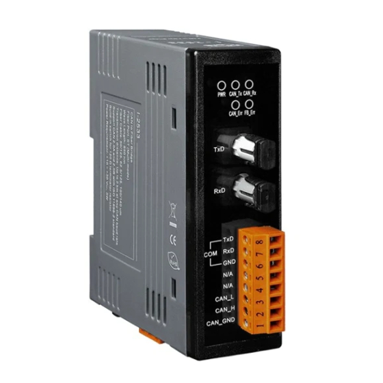
Only for utility tool COM Port ISO 11898-2 standard Power Connector port +10 ~ +30V between +VS and GND DIP Switch Enable or disable 120Ω terminator resistor Figure 2-2 Appearance of I-2533 I-2533 [V2] User Manual (ver. 2.0, 2021/10/21) ------8... -
Page 9: Pin Assignment
2.3 Pin Assignment The pin assignments of COM port, CAN port, fiber port and power connector of I-2533 are shown in the following tables. Table 2-1 Pin Assignment Port Name Description TXD pin of RS-232 port. RXD pin of RS-232 port. -
Page 10: Rotary Switch
When users would like to set the CAN baud rate or message filter of I-2533, use the rotary swich on the upper of the power connector to archieve this purpose. Users can find it on the top of the power connector. -
Page 11: Led Indicator
2.5 LED Indicator There are 5 LEDs on the I-2533. One for power indication, three for CAN bus indication and one for fiber indication. The LED assignment and description are shown as follows. Figure 2-4 LED Assignment of I-2533 LED Name... - Page 12 CAN network, the LED is turned off if there is no error happened. Fiber Err 1. If the I-2533 detects the RXD line of the fiber is off, this LED is always on. 2. If the fiber data buffer is overflow, this LED flashes once per second.
-
Page 13: Terminator Resistor Setup
CAN_H CAN_L Figure 2.5 CAN bus network topology Each I-2533 includes one build-in 120Ω termintor resistor, users can decide if it is enabled or not. The DIP switch for terminator resistor is under the power connector. DIP switch for terminator resistor... - Page 14 If your application is like the structure as follows, the terminator resistor is not needed. CAN_H CAN_L I-2533 Device 1 Device 2 Device N Fiber Device 1 Device 2 Device N I-2533 CAN_H CAN_L Figure 2-9 Application 2 I-2533 [V2] User Manual (ver. 2.0, 2021/10/21) ------14...
-
Page 15: Wire Connection
(ISO 11898-2) Figure 2-10 Wire Connection of I-2533 The I-2533 has a metallic board attached to the back of the plastic basket. This metallic board and the F.G. pin of power connector are interconnected inside the I-2533. When users mount the I-2533 onto a metal DIN-Rail, users can connect the DIN-Rail to Earth Ground to replace connecting the F.G. -
Page 16: Network Deployment
3 Network Deployment 3.1 Driving Capability Before introducing the driving capability of I-2533, some characteristics of copper cable must be assumed. The AC parameters are 120Ω impedance and 5 ns/m line delay, and the DC parameter follows the table shown below. -
Page 17: Fiber Selection & Fiber Length
Fiber Length [m] < 2000 < 1500 By the way, when users use I-2533 in their application, they need to use one pair of I-2533 for communication. The general application architecture may look like as follows. Figure 3-1 I-2533 general application architecture... -
Page 18: Filter & User's Baud Rate Configuration
When connecting to the COM port of I-2533, the TxD pin of the cable is connected to the TXD pin of the COM port, RXD pin of the cable is connected to the RXD pin of the COM port, and GND pin of the cable is connected to the GND pin of the COM port. - Page 19 Step2: After connecting the I-2533 successfully, the parameters stored in the I-2533 will be shown on the dialog. Step3: Users can set the baud rate on the “User‟s Baud Rate” field. Here, fill “250000” for 250 kbps or “83333” for 83.333kbps. The I-2533 supports the sample-point configuration.
- Page 20 Step4: The default CAN filters are all disable. It means that I-2533 will receive all CAN messages and those CAN messages will be transfer to the fiber port. The filter configuration is uesed to block certain CAN messages which would not be transfered to the fiber. The filter configuration including the “CAN Mode”, “ACC”...
- Page 21 Step7: Then, Users can save the configurations into .xml file. Click “Save to File” to archieve this purpose. Step8: Of course, users can load the configurations from .xml file, and “Save To I-2533” to store them into the I-2533. I-2533 [V2] User Manual (ver. 2.0, 2021/10/21) ------21...
- Page 22 Step9. After finishing the configuration, set the rotary switch value to “0” ~ “A” and reboot the I-2533. The CAN message filter will be applied automatically in the value “0” ~ “A” of the rotary switch. The CAN baud rate set by utility is only appled when the rotary switch is set to “A”.
-
Page 23: Can Message Filter Configuration
3.4 CAN Message Filter Configuration The I-2533 supports the CAN message filter configuration. By using the filter, the I-2533 will not receive unwanted CAN messages. The filter configuration has “Acceptance Code” and “Acceptance Mask” filed. It can filter useless CAN messages by combining these two setting. - Page 24 1111 1111 1111 1111 bit) There are 30 filter settings. The incoming CAN message pass one of the filtering rule. The I-2533 will receive this message. Here shows the example (2) and (3) above. I-2533 [V2] User Manual (ver. 2.0, 2021/10/21) ------24...
-
Page 25: Update Firmware
I-2533. You can get these files from the following website https://www.icpdas.com/en/download/index.php?model=I-2533 Step 1: Power off the I-2533, set the rotary switch to „E‟, and power on the I-2533. If the I-2533 is in the firmware update mode, the CAN_Tx, CAN_Rx, CAN_Err, FB_Err will flash once per second simulationously. -
Page 26: Dimension
4 Dimension Figure 4-1 Dimension of I-2533 I-2533 [V2] User Manual (ver. 2.0, 2021/10/21) ------26...
Need help?
Do you have a question about the I-2533 and is the answer not in the manual?
Questions and answers