Table of Contents
Advertisement
Quick Links
www.pce-industrial-needs.com
Tursdale Technical Services Ltd
Unit N12B
Tursdale Business Park
Co. Durham
DH6 5PG
United Kingdom
Phone: +44 ( 0 ) 191 377 3398
Fax:
+44 ( 0 ) 191 377 3357
info@tursdaletechnicalservices.co.uk
http://www.industrial-needs.com/
Manual
Graphic AC Power Quality Analyzer
PCE-GPA 62
Advertisement
Table of Contents

Related Manuals for PCE Health and Fitness PCE-GPA 62


Summary of Contents for PCE Health and Fitness PCE-GPA 62
- Page 1 Tursdale Technical Services Ltd Unit N12B Tursdale Business Park Co. Durham DH6 5PG United Kingdom Phone: +44 ( 0 ) 191 377 3398 Fax: +44 ( 0 ) 191 377 3357 info@tursdaletechnicalservices.co.uk http://www.industrial-needs.com/ Manual Graphic AC Power Quality Analyzer PCE-GPA 62...
- Page 2 info@tursdaletec chnicalservices.co o.uk PCE In ndustria al Needs SYM MBOLS sh howed on t the clamp p meter or in this ma anual: Caut tion, risk of f danger. Refe er to accom mpanying d documents Caut tion, risk of f electric sh hock.
- Page 3 info@tursdaletechnicalservices.co.uk Overvoltage Category I (CAT I): Equipment for connection to circuits in which measures are taken to limit the transient overvoltage’s to an appropriate low level. Overvoltage Category II (CAT II): Energy-consuming equipment supplied from fixed installation. Overvoltage Category III (CAT III): Equipment in fixed installations.
-
Page 4: Table Of Contents
info@tursdaletechnicalservices.co.uk Table of contents I. Features ..............................6 II. Panel Description ..........................7 III. Operating Instructions ........................8 III.1 Setup ............................8 III.2 Measurement of RMS value, THD-F and Harmonics of ACV ..........14 III.3 Measurement of RMS value, THD-F and Harmonics of ACA ..........17 ... - Page 5 info@tursdaletechnicalservices.co.uk...
-
Page 6: Features
info@tursdaletechnicalservices.co.uk I. Features Power Quality Analysis for Single and Balanced Three Phase System. Harmonic Analysis of Voltage and Current (1 to 50 order). c. True RMS measurement of V with 0.5% of reading basic accuracy. True RMS measurement of A with 1% of reading basic accuracy Graphic Waveform of Voltage and Current f. -
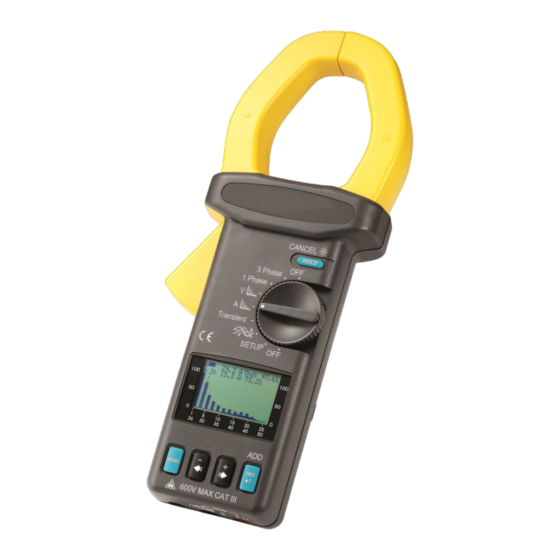
Page 7: Panel Description
info@tursdaletechnicalservices.co.uk II. Panel Description 600V V L1 1. Jaw Assembly 2. Trigger Press the trigger to open the jaw assembly. 3. HOLD/CANCEL/BACK LIGHT Press this button to HOLD the display in LCD, or turn the backlight on or off. It is also used to delete harmonics in the harmonics configuration 4. -
Page 8: Operating Instructions
info@tursdaletechnicalservices.co.uk 9. FUNC Button Press this button to select different display. 10. V Input Terminal This terminal is used as input for voltage. 11. COM Terminal This terminal is used as common voltage reference input. 12. RS-232 window and Battery Cover III. - Page 9 info@tursdaletec chnicalservices.co o.uk ENT TIME: T There is a ca alendar clock k inside the m meter. Users should setup p the correct t time. CURR HOUR MINUT LE: Setup th he sampling i interval in se econds for Da atalogging.
- Page 10 i info@tursdaletec c hnicalservices.co o.uk MINUT TIME: sched dule when to o stop datalog gging STOP HOUR MINUT VT: set t the ratio of voltage trans sformer, norm mally 1. V (readi ing) = Voltag ge * VT...
- Page 11 info@tursdaletec chnicalservices.co o.uk MD: se et the time in nterval form m maximum de mand in min nutes (1 to 60 0 minutes), n normally 15. HZ: se et the operati ng frequency y to 50Hz, 60 0Hz, or Auto FF: enable (1 1) or disable (0) auto-pow...
- Page 12 info@tursdaletec c hnicalservices.co o.uk TOLERA ANCE HARM ONICS CON N FIGURATIO O N: select th he harmonics s to be logge...
- Page 13 info@tursdaletec chnicalservices.co o.uk E: The unit w will adjust the e sampling tim me according g to the amo ount of NOTE harm onics to be lo ogged ON: set the po oints to be lo ogged for eac ch cycle of th he waveform .
-
Page 14: Iii.2 Measurement Of Rms Value, Thd-F And Harmonics Of Acv
info@tursdaletechnicalservices.co.uk III.2 Measurement of RMS value, THD-F and Harmonics of ACV 600V Voltage: a. Set the rotary switch at V position. b. Insert the test leads into the input jack. Connect the test prods of the test leads in PARALLEL to the circuit to be measured. - Page 15 info@tursdaletec c hnicalservices.co o.uk %THD- -F: Total Har rmonic Distor rtion with res spect to Fund damental fre quency -F = ( √ (V2 %THD- + … +V + V50 / V1) * 100 Where, 1: magnitude e at the nomi inal frequenc cy (eg.50 or 6 60 Hz)
- Page 16 info@tursdaletec chnicalservices.co o.uk Frequency ( (Hz) is displa ayed in the se e cond page (Harmonics order NOTE: order).
-
Page 17: Iii.3 Measurement Of Rms Value, Thd-F And Harmonics Of Aca
info@tursdaletechnicalservices.co.uk III.3 Measurement of RMS value, THD-F and Harmonics of ACA a. Set the rotary switch at A position. b. Clamp on to the conductor, and read the data from LCD display. WARNING: Make sure that all the test leads are disconnected from the meter's terminals for current measurement. - Page 18 info@tursdaletec chnicalservices.co o.uk %THD- -F: Total Har rmonic Distor rtion with res spect to Fund damental fre quency -F = ( √ (V2 %THD- + … +V + V50 / V1) * 100 Where, 1: magnitude e at the nomi inal frequenc cy (eg.50 or 6 60 Hz)
- Page 19 info@tursdaletec c hnicalservices.co o.uk NOTE: Freq quency (Hz) i s displayed in the secon d page (Harm m onics orde to 50 order).
-
Page 20: Iii.4 Waveforms Of Acv And Aca With Phase Angle (Φ)
info@tursdaletechnicalservices.co.uk III.4 Waveforms of ACV and ACA with Phase Angle (φ) When users set the rotary switch at waveform position, the unit will display both voltage and current waveform with phase angle. -
Page 21: Iii.4.1 Waveform Of Acv With Peak Value
info@tursdaletec chnicalservices.co o.uk ress the + ► Users can p or -◄ button ns to move th he 0 referenc ce axis of cu rrent up or d down. So the e waveforms of voltage an nd current ca an be easily d distinguished d as in the fo ollowing figur... -
Page 22: Iii.5 Measurement Of Single Phase Ac Power Quality
info@tursdaletechnicalservices.co.uk III.5 Measurement of Single Phase AC Power Quality NOTE: If the peak value of the input AC current or AC voltage is greater than the maximum value of the range, then symbol of OL will be displayed. NOTE: If the VT ratio is not 1, the readings of shown in LCD is equal to the W, VA, and VAR values measured by the tester multiplied by VT ratio (W = W ×... -
Page 23: Iii.5.1 True Power (W) And Power Factor (Pf)
info@tursdaletechnicalservices.co.uk III.5.1 True Power (W) and Power Factor (PF) III.5.2 Apparent Power (VA, KVA) and Reactive Power (VAR, KVAR) III.5.3 Maximum Demand (KW and KVA) -
Page 24: Iii.5.4. Energy (Kwh, Pfh, Kvarh, And Kvah)
info@tursdaletechnicalservices.co.uk WARNING: Must disable auto-power-off for this measurement. III.5.4. Energy (KWh, PFh, KVARh, and KVAh) WARNING: Must disable auto-power-off for this measurement. III.5.5 Phasor Diagram III.5.6 RMS values of Voltage and Current... -
Page 25: Iii.6 Measurement Of Balanced 3 Phase Ac Power Quality
info@tursdaletechnicalservices.co.uk III.6 Measurement of Balanced 3 Phase AC Power Quality a. Set the rotary switch at the 3 Phase position b. Connect the test leads to the voltage source in parallel with the load. c. Clamp on one of the wire to the load. The current should flow from the front of the tester to the side of the battery cover d. -
Page 26: Iii.6.2 Apparent Power (Va, Kva) And Reactive Power (Var, Kvar)
info@tursdaletechnicalservices.co.uk III.6.2 Apparent Power (VA, KVA) and Reactive Power (VAR, KVAR) III.6.3 Maximum Demand (KW and KVA) WARNING: Must disable auto-power-off for this measurement. III.6.4 Energy (KWh, PFh, KVARh, and KVAh) WARNING: Must disable auto-power-off for this measurement. -
Page 27: Iii.6.5. Phasor Diagram
info@tursdaletechnicalservices.co.uk III.6.5. Phasor Diagram III.6.6. RMS values of Voltage and Current IV. DATALOGGING of Voltage (RMS value) and Harmonics IV.1 Scheduled Datalogging Set the rotary switch at the V position and press the REC button ONCE. If users see the following display and press the REC button, the true RMS value of voltage and selected harmonics set in the configuration will be logged at specified sampling interval. - Page 28 info@tursdaletechnicalservices.co.uk When the REC button is pressed, users will see the following display.
- Page 29 info@tursdaletechnicalservices.co.uk Users always have 8 seconds to cancel Datalogging by pressing the HOLD button for about 2 seconds. If users do not press HOLD/CANCEL button, the unit starts Datalogging, and the LED next to the REC button starts blinking.
-
Page 30: Iv.2 Immediate Datalogging
info@tursdaletechnicalservices.co.uk IV.2 Immediate Datalogging Press the REC button TWICE START TIME will be changed to next minute. STOP TIME will be changed to current time tomorrow. Please refer to HARMONICS CONFIGURATION of SETUP for selecting harmonics. V. DATALOGGING of Current (RMS value) and Harmonics V.1 Scheduled Datalogging Set the rotary switch at the A position and press the REC button ONCE. - Page 31 info@tursdaletechnicalservices.co.uk When the REC button is pressed, users will see the following display. Users always have 8 seconds to cancel datalogging by pressing the HOLD button for about 2 seconds. If users do not press HOLD/CANCEL button, the unit starts datalogging, and the LED at the bottom starts blinking.
-
Page 32: Immediate Datalogging
info@tursdaletechnicalservices.co.uk Please refer to HARMONICS CONFIGURATION of SETUP for selecting harmonics. NOTE: The true RMS value and the first harmonics are always logged. V.2 Immediate Datalogging Press the REC button TWICE, the unit start Datalogging in the next minute. START TIME will be changed to next minute. STOP TIME will be changed to current time tomorrow. -
Page 33: Vi.2 Datalogging Of Voltage Waveform
info@tursdaletechnicalservices.co.uk VI.2 Datalogging of Voltage Waveform Set the rotary switch at the VA waveform and press the FUNC to select display of voltage waveform. Press the REC button once to do scheduled Datalogging. Voltage waveform will be logged. NOTE: Users can specify how many points per cycle in the WAVEFORM CONFIGURATION of SETUP. -
Page 34: Datalogging Of Transient Detection
info@tursdaletechnicalservices.co.uk NOTE: Users can specify how many points per cycle to be logged in the WAVEFORM CONFIGURATION of SETUP. VII. Datalogging of transient detection Set the rotary switch to the Transient position, the following display is shown. It shows the reference voltage is AC 110.0V (TRANS REF), and the threshold is 5%. If the voltage exceeds 115.5V (SWELL) or is less than 104.5V (DIP), or is less the 40.0V (OUTAGE), one transient event will be logged. - Page 35 info@tursdaletechnicalservices.co.uk Press the FUNC button to start transient detection.
- Page 36 info@tursdaletechnicalservices.co.uk After users press the FUNC button, the LCD will become blank and the LED at the bottom starts to flash.
- Page 37 info@tursdaletechnicalservices.co.uk To stop transient detection and review events, press the FUNC button again. Press the + ►or -◄ buttons to review events.
-
Page 38: Datalogging Of Ac Power
info@tursdaletechnicalservices.co.uk VIII. Datalogging of AC POWER VIII.1 Scheduled Datalogging Press the REC button ONCE... - Page 39 info@tursdaletechnicalservices.co.uk Users can press the REC button once to start scheduled datalogging. The START TIME and STOP TIME is set in the SETUP. When the REC button is pressed, users will see the following display. Users always have 8 seconds to cancel Datalogging by pressing the HOLD button for about 2 seconds. If users do not press HOLD/CANCEL button, the unit starts Datalogging, and the LED next to the REC button starts blinking.
-
Page 40: Viii.2 Immediate Datalogging
info@tursdaletechnicalservices.co.uk The unit will log 50,000 records of (Date/Time, VA, W, VAR, PF, KVAH, KWH, KVARH, PFH, AD(VA), AD(W), MD(VA), MD(W), Phase, HP). VIII.2 Immediate Datalogging Press the REC button TWICE START TIME will be changed to next minute. STOP TIME will be changed to current time tomorrow. -
Page 41: Clear Data Memory
info@tursdaletechnicalservices.co.uk IX. CLEAR DATA MEMORY To clear the memory of data logger, hold the REC button and turn the power on. The following display will be shown in LCD. Users press the HOLD button to confirm the clearance of memory. The unit is turned off after the memory is cleared. - Page 42 info@tursdaletechnicalservices.co.uk For VT ≠ 1, the accuracy in percentage is the same (±1%). But the additional wattage should be multiplied by the VT ratio. For example, ±0.2VA becomes ±0.2VA * VT ratio AC Reactive Power (VAR, from 0.000 VAR to 9999 KVAR) Range (0 to 1500A) Resolution Accuracy of Readings...
- Page 43 info@tursdaletechnicalservices.co.uk Harmonics of AC Current in Magnitude (1 to 50 order, minimum current at 50 or 60 Hz > 20A) Range Resolution Accuracy 1 – 20 0.1% ±2% of reading ±0.4A 21 – 50 0.1% ±4% of reading ±0.4A Power Factor (PF) Range Resolution Accuracy...
-
Page 44: Battery Replacement
info@tursdaletechnicalservices.co.uk XII. Battery Replacement When the battery voltage low is shown in LCD, A. Turn the power off and remove the test leads from the box. B. Remove the screw of the battery compartment. C. Lift and remove the battery compartment. D. -
Page 45: Maintenance & Cleaning
info@tursdaletechnicalservices.co.uk XIII. Maintenance & Cleaning Servicing not covered in this manual should only be performed by qualified personnel. Repairs should only be performed by qualified personnel. Periodically wipe the case with a damp cloth and detergent; do not use abrasives or solvents. Address of Agent, Distributor, Importer, or Manufacturer In this direction will find a vision of the measurement technique: http://www.industrial-needs.com/measuring-instruments.htm...
Need help?
Do you have a question about the PCE-GPA 62 and is the answer not in the manual?
Questions and answers