
Related Manuals for Ceco Fybroc 1530 Series


Summary of Contents for Ceco Fybroc 1530 Series
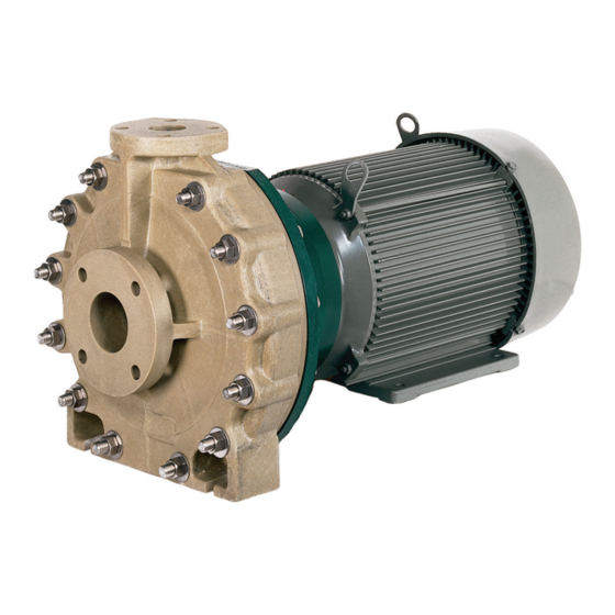
- Page 1 CECO Fybroc FYBROC® SERIES 1530 HORIZONTAL INSTALLATION OPERATION MAINTENANCE MANUAL DO NOT INSTALL, OPERATE OR SERVICE THIS PUMP BEFORE READING THE ENTIRE MANUAL...
-
Page 2: Table Of Contents
INDEX Fybroc Warranty ..............3 Assembly/Disassembly Procedures ........13 Safety .................4 General ..............13 Installation Instructions .............8 Disassembly ............13 Location ..............8 Assembly ...............14 Foundation ...............8 John Crane Type 8B2 ........14 Piping the Pump ............9 John Crane Type 8-1T ........15 Suction Piping ..........9 John Crane Type 8-D ........15 Impeller Adjustment ..........16 Discharge Piping ..........9 Ancillary Piping ..........9... -
Page 3: Fybroc Warranty
All illustrations and provisions in specifications are descriptive and are not intended as warranties. Penalty of any kind are not acceptable unless approved in writing by an officer of CECO Environmental Corporation. -
Page 4: Safety
INSTALLATION. MISUSE OR IMPROPER STORAGE, INSTALLATION OR OPERATION OF PUMPS MAY RESULT IN CAUTION SERIOUS LOSS OR DAMAGE. CECO FYBROC PUMP SYMBOL REPRESENTS THE ATEX MARKING FOR DIVISION IS NOT RESPONSIBLE FOR ANY LOSS OR EXPLOSIVE ATMOSPHERE ZONES. DAMAGE RESULTING FROM CAUSES BEYOND ITS... - Page 5 SAFETY WARNING: ROTATING EQUIPMENT KEEP GUARDS IN WARNING LABELS AND TAGS PLACE The following warning labels are affixed ALL GUARDS SHOULD BE KEPT IN PLACE AND SECURE to the pump by the manufacturer. DURING OPERATION. NEVER SHOULD THE EQUIPMENT BE ENERGIZED WITHOUT THE GUARDS IN PLACE AND SECURE.
- Page 6 SAFETY RECEIVING AND INSPECTION STORAGE The Products of CECO Fybroc Pump Division are subject PUMPS MUST BE PROPERLY COVERED AND to thorough and rigorous quality control and inspection PROTECTED AGAINST MOISTURE, DIRT, AND CAUTION procedures throughout the whole of the manufacturing...
- Page 7 SAFETY 1500 / 1530 - Noise Characteristics Typical Sound Pressure Levels 3500 2900 1750 1450 PUMP & PUMP & PUMP & PUMP & PUMP PUMP PUMP PUMP MOTOR MOTOR MOTOR MOTOR 0.55 < .75 0.75 18.5 Sound pressure level LpA measured at 1m reference distance from pump Tolerance = +/- 3 dBA...
-
Page 8: Installation Instructions
INSTALLATION HORIZONTAL PUMPS LOCATION TABLE 1 The pump should ideally be placed as close as possible Base Units Bolt Size to the liquid supply source. Allow sufficient space on the Plate sides and overhead to permit inspection and maintenance inch 19.5 2.63 0.75... -
Page 9: Piping The Pump
INSTALLATION HORIZONTAL PUMPS PIPING THE PUMP D) Elbows, fittings, valves or expansion joints should be avoided at the suction flange. Allow a straight run All flanged connections to the pump should be full of at least 10 pipe diameters into the suction of the flat face with full contact gaskets. -
Page 10: Electrical Connections
INSTALLATION HORIZONTAL PUMPS ELECTRICAL CONNECTIONS A) All electrical work done to the unit should be done by a qualified electrician. All local, state and federal electrical codes should be adhered to. B) Wire motor according to motor manufacturers instructions. Ensure that all connections and covers are tight and that proper sized wire and switch-gear are used. -
Page 11: Start-Up And Operating Procedures
START-UP AND OPERATING PROCEDURES LUBRICATION OPERATIONAL CHECK LIST On a close coupled pump only the motor requires A) Periodically check mechanical seals for proper lubrication. Since all motors come from the factory pre- operation. lubricated there is no action required. B) Periodically check lubrication to the motor bearings. -
Page 12: Trouble Check List
START-UP AND OPERATING PROCEDURES TROUBLE CHECK LIST Refer to the following diagnostic section if hydraulic problems are encountered in the pump operation. PROBLEM: Not enough liquid, or no liquid delivered. CHECK: Suction pipe and /or pump casing not filled with liquid. Speed too low. -
Page 13: Assembly/Disassembly Procedures
ASSEMBLY/DISASSEMBLY PROCEDURES FOR HORIZONTAL PUMPS GENERAL 3) Remove the cover o-ring (Item 73) and place in a container with the casing hardware. The Fybroc pump is designed for easy inspection and service because of its back pullout construction. For 4) To disassemble the impeller assembly, remove the inspection or replacement of certain parts, the work locking ring (Item 14 B) by removing the two Allen can be done in place, without the necessity to remove... -
Page 14: Assembly
ASSEMBLY/DISASSEMBLY PROCEDURES FOR HORIZONTAL PUMPS ASSEMBLY 10) The Fybroc pump, as standard, is equipped with a single outside seal with stationary seal face and 1) Inspect casing, cover and impeller for any damage rotating compression unit, or a double inside seal and make sure all sealing surfaces are free of dirt with stationary seal faces and rotating double and scratches. -
Page 15: John Crane Type 8-1T
ASSEMBLY/DISASSEMBLY PROCEDURES FOR HORIZONTAL PUMPS 8) Rotate the motor shaft manually while pushing on the tighten the casing bolts. motor shaft to take up any shaft end float. Confirm 10) Rotate the motor shaft manually while pushing on the no binding exists. Ensure that the seal faces are motor shaft to take up any shaft end float. -
Page 16: Impeller Adjustment
ASSEMBLY/DISASSEMBLY PROCEDURES FOR HORIZONTAL PUMPS 9) Install cover o-ring (Item 73), casing (Item 1) and E) Continue this procedure until the impeller starts secure with the casing bolts, nuts and washers (Items to contact the casing. At this point replace the 1C, 1D, 1E). -
Page 17: Operational Start-Up Checklist
OPERATIONAL START-UP CHECKLIST SERIES 1530 HORIZONTAL PUMPS ❏ Foundation level and baseplate grouted. ❏ Foundation bolts tight. ❏ Motor and pump mounting bolts tight. ❏ Suction and discharge connections secure. ❏ Flush piping installed if required. ❏ Electrical connections secure and covered. ❏... -
Page 18: Sectional Drawings
1530 SERIES GROUP 1... -
Page 19: 1530 Group Ii
1530 SERIES GROUP 2... -
Page 20: Typical Mechanical Seal Installations
1530 SERIES SEAL AND STUFFING BOX ARRANGEMENTS PRODUCT FLUSH: A portion of the pumped fluid is re-circulated through the stuffing box to provide lubrication and cooling to the seal. Use plastic fittings only. FLUSH FROM PUMP DISCHARGE SINGLE OUTSIDE-DRILLED, SINGLE OUTSIDE-SOLID CLAMPED SEAT CLAMPED SEAT WITH CASING WITH INTERNAL COVER FLUSH BYPASS FLUSH... -
Page 21: External Flush
1530 SERIES SEAL AND STUFFING BOX ARRANGEMENTS EXTERNAL FLUSH: An external source of clean fluid is required at the stuffing box to provide lubrication and cooling. Use plastic fittings only. FLUSH FROM FLUSH FROM EXTERNAL EXTERNAL SOURCE SOURCE SINGLE OUTSIDE-DRILLED & SINGLE INSIDE-SOLID O-RING SEAT CLAMPED SEAT W/EXTERNAL FLUSH W/EXTERNAL FLUSH... -
Page 22: Mechanical Seal Piping/Flow Requirements
FLUSH PIPING FOR SINGLE MECHANICAL SEAL OPTIONAL PRESSURE REGULATOR Y SEDIMENT PRESSURE GUAGE STRAINER VALVE FLOW METER IN IN IN IN FLUSH PIPING FLUSH PIPING FLUSH PIPING FLUSH PIPING SINGLE SINGLE SINGLE SINGLE MECHANICAL SEAL MECHANICAL SEAL MECHANICAL SEAL MECHANICAL SEAL FLUSH FLOW RATE FOR SINGLE SEAL FLUSH PRESSURE = 15 TO 25 PSI ABOVE SEAL CHAMBER PRESSURE FLUSH LIQUID TEMPERATURE = 125oF (50oC) MAXIMUM... -
Page 23: Double Mechanical Seal
FLUSH PIPING FOR DOUBLE INSIDE MECHANICAL SEAL PRESSURE GUAGE NEEDLE VALVE TO CONTROL BOX PRESSURE FLUSH PIPING FLUSH PIPING FLUSH PIPING FLUSH PIPING DOUBLE INSIDE DOUBLE INSIDE DOUBLE INSIDE MECHANICAL SEAL MECHANICAL SEAL MECHANICAL SEAL MECHANICAL SEAL OPTIONAL PRESSURE REGULATOR IN IN IN IN Y SEDIMENT FLOW METER... -
Page 24: Eu Declaration Of Conformity
EU DECLARATION OF CONFORMITY... -
Page 25: Read Warning
If you do not have personnel who are capable of safe quality repair of this equipment, we advise you to Do not attempt to manufacture parts or modify CECO Fybroc Pump parts in any manner. Death, personal injury, and/ return the equipment to CECO Fybroc PUMP to be repaired. - Page 26 CECO Fybroc CECO Fybroc Pump 700 Emlen Way • Telford, PA 18969 TOLL-FREE: (215) 723-8155 • (800) FYBROC-1 • (215) 723-2197 infoFHS@onececo.com • https://www.cecoenviro.com/fybroc...
Need help?
Do you have a question about the Fybroc 1530 Series and is the answer not in the manual?
Questions and answers