
Related Manuals for Ceco Dean Pump pH2110 Series


Summary of Contents for Ceco Dean Pump pH2110 Series
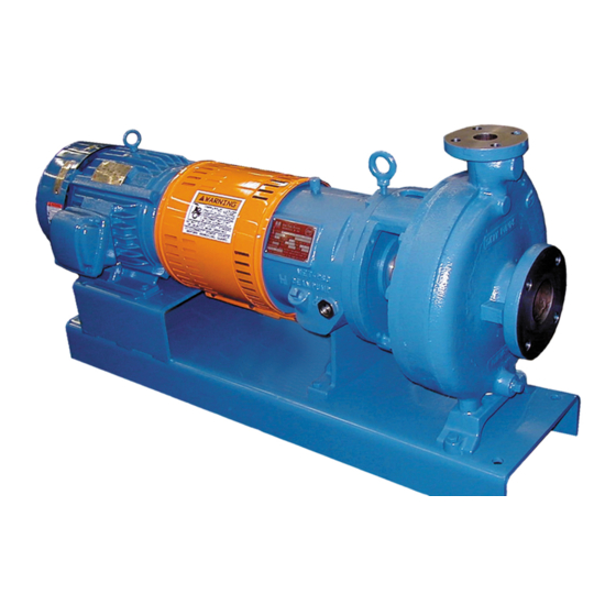
- Page 1 ® ERIES P Horizontal Process Pumps DO NOT INSTALL, OPERATE, OR SERVICE THIS PUMP BEFORE READING THE ENTIRE MANUAL Instruction Manual MC 1.2.35...
-
Page 2: Table Of Contents
INDEX Mechanical Design Specifications ........1 Standard Materials of Construction . -
Page 3: Mechanical Design Specifications
SERIES HORIZONTAL PROCESS PUMPS STANDARD, HORIZONTAL, SINGLE STAGE, END SUCTION, OPEN IMPELLER, CENTRIFUGAL PROCESS PUMPS pH2110 Series: Types pH2111, 2112, 2114, 2116, 2117, 2118 • pH2140 Series: Types pH2141, 2142, 2144, 2146, 2147, 2148 pH2170 Series: Types pH2171, 2172, 2174, 2176, 2177, 2178 • pH3170 Series: Types pH3171, 3172, 3174, 3176, 3177, 3178 pH2180 Series: Types pH2181, 2182, 2184, 2186, 2187, 2188 ECHANICAL ESIGN... -
Page 4: Working Pressure Vs. Pumping Temperature
SERIES HORIZONTAL PROCESS PUMPS WORKING PRESSURE/PUMPING TEMPERATURE MAXIMUM ALLOWABLE WORKING PRESSURE CURVES H2110, H2140, H2170, HP2110, HP2140 H3170 H2180... -
Page 5: Product Inspection And Test
PRODUCT INSPECTION AND TEST The Products of Dean Pump Division are subject to thorough and rig- and tagged with a signed certificate of inspection prior to shipment. orous quality control and inspection procedures through out the Each pump when shipped is ready to perform the service for which whole of the manufacturing process to assure proper operation in full it was designed with minimum maintenance and expense if properly conformity with established performance stand ards. -
Page 6: Installation
INSTALLATION Always wear the appropriate protective apparel when working on BASEPLATE MOUNTING AND ALIGNMENT or around the pumping equipment. Safety glasses with side shields, The sequence of mounting which must be observed for proper base- heavy work gloves (use insulated work gloves when handling hot plate and pump mounting is: items), steel-toed shoes, hard hat, and any other protective gear as 1) Place baseplate, with pump and driver mounted thereon, on the... -
Page 7: Suction And Discharge Piping
piping to remove the distorting load, and realign the pump able to the pump and should be considered at the time the system and driver. is designed. 9) The pump and driver alignment must again be checked at the NOTE: See page 26 for Installation of pHP self-priming pumps. operating temperature and alignment corrected under the hot PUMP AND DRIVER ALIGNMENT condition. -
Page 8: Allowable Nozzle Loads
To check the offset alignment, mount the dial indicator as above After each change, it is necessary to recheck both angular and except with the indicator button on an outside diameter of the sta- offset alignment of the coupling. After driver is aligned to the tionary coupling hub. -
Page 9: Instructions For Use Of Allowable Loads
INSTRUCTIONS FOR USE OF ALLOWABLE LOADS 6) If the base plate is un-grouted, nonmetallic, and is anchored down, multiply the original values of Table 2 by 70%. 1) Determine the applied nozzle loads from the suction and dis- Compare these values with the Table 2 corrected values of charge piping systems. - Page 10 1 – A ABLE LLOWABLE NDIVIDUAL OZZLE OADS Suction Discharge ANSI Pump Size Forces (lb) Moments (ft-lb) Forces (lb) Moments (ft-lb) Size PH2110 1050 1350 3000 x3x6 1050 1240 1250 1350 3000 2x3x6 1050 1240 1250 1350 3000 1050 1210 1210 1350 3000...
- Page 11 2 – A ’ ABLE LLOWABLE OMBINATION OZZLE OADS FOR OZZLE TRESS TRESS LIPPAGE ON ASEPLATE Suction Discharge ANSI Pump Size Forces (lb) Moments (ft-lb) Forces (lb) Moments (ft-lb) Size PH2140 (con’t) x3x13 2700 1350 3060 3730 2020 1350 6240 2x3x13 1920 1230...
-
Page 12: Pump Cooling Requirements
PUMP COOLING REQUIREMENTS Pumps are furnished with optional seal chamber jacket, jacketed MECHANICAL SEAL GLAND COOLING casing, jacketed mechanical seal gland, and bearing housing cool- Mechanical seal gland cooling is generally applied under the same ing coil according to the pump service. conditions as those for seal chamber cooling. -
Page 13: Pump Heating Requirements
PUMP HEATING REQUIREMENTS The optional seal chamber, mechanical seal gland, and pump When steam is used as the heating medium, inlet piping should be casing jackets may be used to provide pump heating. The jack- run to the highest jacket connection and outlet should be from the ets are good for pressure to 125 psig and may be used with lowest connection to allow condensate to drain. -
Page 14: Pump Start Up Check List
caught and thrown by the rotating parts when the pump is started. WARNING: Bolt the coupling guard securely into place, checking to assure that it Do not operate a pump at a low flow condition, unless provision has is not contacting any parts that will rotate when the pump is started. been made to prevent dangerous heat build up within the pump casing. -
Page 15: Pump Designation Code For Ph2110
PUMP DESIGNATION CODE FOR PH2110 H2111 pH2111 Pump with Standard Seal UMP WITH TANDARD HAMBER P Chamber (no jacketing) pH2112 Pump with Jacketed Seal Chamber pH2114 Pump with Jacketed Seal Chamber and Bearing Housing Oil Cooler pH2116 Pump with Large Bore Seal Chamber pH2117 Pump with Jacketed Seal Chamber and Jacketed Casing... -
Page 16: Pump Designation Code For Ph2140
PUMP DESIGNATION CODE FOR PH2140 pH2141 Pump with Standard Seal H2141 UMP WITH TANDARD HAMBER P Chamber (no jacketing) pH2142 Pump with Jacketed Seal Chamber pH2144 Pump with Jacketed Seal Chamber and Bearing Housing Oil Cooler pH2146 Pump with Large Bore Seal Chamber pH2147 Pump with Jacketed Seal Chamber and Jacketed Casing... -
Page 17: Pump Designation Code For Ph2170/Ph3170
PUMP DESIGNATION CODE FOR PH2170/pH3170 pH2171/pH3171 Pump with Standard Seal Chamber (no jacketing) pH2176/pH3176 Pump with Large Bore Seal Chamber pH2172/pH3172 Pump with Jacketed Seal Chamber pH2177/pH3177 Pump with Jacketed Seal Chamber and Jacketed Casing pH2174/pH3174 Pump with Jacketed Seal Chamber and Bearing pH2178/pH3178 Pump with Jacketed Seal Chamber, Jacketed Casing, Housing Oil Cooler... -
Page 18: Pump Designation Code For Ph2180
PUMP DESIGNATION CODE FOR PH2180 pH2181 Pump with Standard Seal Chamber (no jacketing) pH2186 Pump with Large Bore Seal Chamber pH2182 Pump with Jacketed Seal Chamber pH2187 Pump with Jacketed Seal Chamber and Jacketed Casing pH2184 Pump with Jacketed Seal Chamber and Bearing pH2188 Pump with Jacketed Seal Chamber, Jacketed Casing, Housing Oil Cooler... -
Page 19: Disassembly And Assembly Procedures
DISASSEMBLY AND RE-ASSEMBLY PROCEDURES the motor support (83) when they are separated from the WARNING: pump. Hook a lifting hoist to the lifting eye(s) of the motor and Work must be performed only by thoroughly trained and qualified personnel to assure quality repair and to reduce the possibilities of take the slack out of the cable or chain. - Page 20 also possible that the isolation valves are not sealing and therefore Use mechanical lifting equipment to lift assemblies and components. allowing liquid to flow from the system into the pump. Personal Do not apply heat to parts to assist in disassembly. Explosion could injury, death and/or equipment damage may occur if great caution occur causing personal injury, death, and/or damage to equipment.
- Page 21 l) Place the shaft assembly in a hydraulic press and remove the equipment may occur. radial bearing (25) by pressing it off of the pump shaft (29). Do Do not attempt to manufacture parts or modify Dean Pump parts in not hammer on the bearings in any way as it may result in seri- any manner.
- Page 22 j) If the pump is of the pH2110 or pHP2110 series, install the end cover (28) so that the “expulsion port” of the rear labyrinth tapered retaining ring (75A) into the groove in the pump shaft seal (76A) is towards the bottom of the bearing housing (26). (29) with the tapered side away from the bearing.
- Page 23 y) If the pump is to be sealed with packing, slide the packing ai) Rotate the pump shaft by hand to be sure there is no internal gland (13) over the pump shaft (29) and up against the front rubbing or binding. labyrinth seal (76).
- Page 24 as) Remove all blocks and wedges while maintaining support with weight of the unit seats the bearing housing foot (9) firmly a hoist. Gently and carefully lower the hoist enough to allow against the baseplate. Tighten the casing bolting evenly to the the weight to seat the supporting feet onto the baseplate.
-
Page 25: Installation And Maintenance Of Seal Chamber Packing
INSTALLATION AND MAINTENANCE OF SEAL CHAMBER PACKING The proper installation and maintenance of packing to seal a pump ACKED HAMBER WITH ANTERN shaft is not difficult but must be properly done to provide good pack- ing and pump shaft sleeve life. All packing must be allowed to leak. This leakage is the only lubrication for the packing and additionally provides cooling to remove part of the frictional heat built up between the shaft sleeve and the packing. -
Page 26: Usual Causes Of Packing Failure And Excessive Seal Chamber Leakage
Foil wrapped packing sets are furnished with soft rings of fibrous the running-in period. Allow sufficient leakage to assume good packing which are placed between the hard metallic rings in the lubrication during the adjustment. Pull up the gland stud nuts locations shown in the diagrams. -
Page 27: Single Outside Unbalanced Seals
To position the Teflon mounted insert, lubricate the inside of the Put the mechanical seal rotary unit on the shaft and slide it back mechanical seal gland. Carefully slide the Teflon mounting ring into against the splash collar. Assemble the seal insert gasket (326), the position in the gland and then slide the insert into place. -
Page 28: Spare Parts
Double seals require a liquid in the seal chamber between the seal Leakage from the outboard seal can be easily spotted. Leakage inserts to provide lubrication. This barrier liquid must be supplied at a through the inboard seal can be detected only by the loss of the bar- pressure of 10 to 15 psi above seal chamber throat pressure to rier (lubricating) liquid from between the seals. -
Page 29: Php2110/Php2140 Pump Sectional Views
HP2110 HP2140 SECTION NO. SECTION NO. 01951B 01947C ’ USTOMER LANT AINTENANCE ECORD Dean Pump Serial Number Service Plant Property Number Location Capacity ; T.D.H. ; Imp. Dia. ; Temp. ; RPM Materials of Construction: Casing ; Impeller ; Shaft ;... - Page 30 One example of other gear would be breathing Use only Dean Pump Division of Met-Pro Corporation parts. apparatus when working near toxic materials. Use only top quality tools. ® IS A REGISTERED TRADEMARK OF CECO ENVIRONMENTAL ©COPYRIGHT 2012 CECO ENVIRONMENTAL, DEAN PUMP 09-5924 512 DE N PUMP...
Need help?
Do you have a question about the Dean Pump pH2110 Series and is the answer not in the manual?
Questions and answers