
Related Manuals for Ceco Dean Pump R4000 Series


Summary of Contents for Ceco Dean Pump R4000 Series
- Page 1 R4000 ® ERIES Horizontal Process Pumps DO NOT INST LL, OPER TE, OR SERVICE THIS PUMP BEFORE RE DING THE ENTIRE M NU L Instruction Manual MC 1.4.43...
- Page 2 INDEX Product Inspection and Test Product Warranty Warnings Receiving Pump Storage Mechanical Design Specifications Installation pplication and Reapplication Pump Foundation Baseplate Mounting and lignment Suction and Discharge Piping Pump and Driver lignment llowable Piping Loads Pump Cooling Requirements Seal Chamber Cooling Mechanical Seal Gland Cooling Bearing Housing Cooling Casing-Pedestal Cooling...
- Page 3 PRODUCT INSPECTION ND TEST The Products of Dean Pump Division are subject to thorough and rig- and tagged with a signed certificate of inspection prior to shipment. orous quality control and inspection procedures through out the Each pump when shipped is ready to perform the service for which whole of the manufacturing process to assure proper operation in full it was designed with minimum maintenance and expense if properly conformity with established performance stand ards.
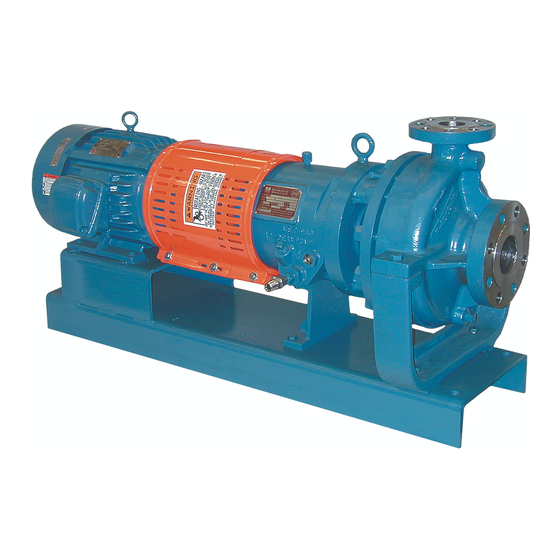
- Page 4 SERIES R4000 HORIZONT L PROCESS PUMPS (317) 293-2930 • E-mail: infofhs@onececo.com ST ND RD, HORIZONT L, SINGLE ST GE, END SUCTION, ENCLOSED IMPELLER, CENTRIFUG L PROCESS PUMPS TYPES R4140, R4170, R4180 ND R4240 MECH NIC L DESIGN SPECIFIC TIONS T ND RD TERI LS OF ONSTRUCTION Direction of Rotation (Viewed from Coupling End) .
- Page 5 INST LL TION lways wear the appropriate protective apparel when working on B SEPL TE MOUNTING ND LIGNMENT or around the pumping equipment. Safety glasses with side shields, The sequence of mounting which must be observed for proper base- heavy work gloves (use insulated work gloves when handling hot plate and pump mounting is: items), steel-toed shoes, hard hat, and any other protective gear as 1) Place baseplate, with pump and driver mounted thereon, on the...
- Page 6 may have forced the pump out of alignment. If so, correct the PUMP ND DRIVER LIGNMENT piping to remove the distorting load, and realign the pump Proper running life of a pump and driver unit depends on the accu- and driver. racy with which the axis of the driver shaft coincides with the axis of the pump shaft when the unit is running.
- Page 7 To check the offset alignment, mount the dial indicator as above fter each change, it is necessary to recheck both angular and offset except with the indicator button on an outside diameter of the sta- alignment of the coupling. fter driver is aligned to the pump, tight- tionary coupling hub.
- Page 8 PUMP COOLING REQUIREMENTS Pumps may be furnished with the following jackets or cooling coil: COOLING W TER PIPING The cooling water piping depends on what cooling coil or jackets 1) Stuffing box are furnished and used. Jackets to be piped in series are, Casing 2) Mechanical seal gland (optional) Pedestal Cooling, Stuffing Box Cooling, and Bearing Housing Cooling, with the cooling water to flow in that sequence.
- Page 9 PIPING CONNECTIONS FOR R4000 SERIES PUMPS Connections (1) and (3) are cooling water inlets. Connections (2) sealed with standard, metal, threaded pipe plugs at the manufactur- and (4) are cooling water outlets. Do not control cooling water flow ing plant. with a valve on connections (1) and/or (3).
- Page 10 PUMP LUBRIC TION Lubrication of the ball type bearings in Dean pumps is by oil upper 1” NPT tapped hole (connection #7 on page 7) on either side contained in the sump of the bearing housing (26). The oil must of the bearing housing.
- Page 11 ST RTING THE PUMP It is important that a pump should never be subjected to thermal or of rotation to be observed. direction of rotation arrow is shown on pressure shock. The liquid should therefore be allowed to flow into the front of the pump casing.
- Page 12 PUMP ST RT UP CHECK LIST These points must be checked after pump installation and before rotation is correct, replace the coupling spacer. If not, connect starting up the pump. the wiring for proper rotation and recheck. 1) Read instruction manual thoroughly and understand it. 7) Check coupling for proper alignment (except for pumps with the optional “C”...
- Page 13 R4140 PUMP WITH J CKETED SE L CH MBER ND BE RING HOUSING OIL COOLER - R4144 R4142 Pump with jacketed seal chamber - R4144 UMP WITH CKETED H MBER E RING OUSING OOLER R4144 Pump with jacketed seal chamber and oil cooler R4146 Pump with large taper bore seal...
- Page 14 PUMP DESIGN TION CODE FOR R4170 R4172 Pump with jacketed seal chamber R4177 Pump with jacketed seal chamber and jacketed casing R4174 Pump with jacketed seal chamber and oil cooler R4178 Pump with jacketed seal chamber, R4176 Pump with large taper bore seal chamber jacketed casing and oil cooler Part No.
- Page 15 PUMP DESIGN TION CODE FOR R4180 R4182 Pump with jacketed seal chamber R4187 Pump with jacketed seal chamber and jacketed casing R4184 Pump with jacketed seal chamber and oil cooler R4188 Pump with jacketed seal chamber, R4186 Pump with large taper bore seal chamber jacketed casing and oil cooler Part No.
- Page 16 PUMP DESIGN TION CODE FOR R4240 R4242 Pump with jacketed seal chamber R4247 Pump with jacketed seal chamber and jacketed casing R4244 Pump with jacketed seal chamber and oil cooler R4248 Pump with jacketed seal chamber, jacketed casing R4246 Pump with large taper bore seal chamber and oil cooler Part No.
- Page 17 DIS SSEMBLY ND SSEMBLY PROCEDURES W RNING: from the pump. Hook a lifting hoist to the lifting eye(s) of the Work must be performed only by thoroughly trained and qualified motor and take the slack out of the cable or chain. Make sure personnel to assure quality repair and to reduce the possibilities of that all of the components of the lifting apparatus are capable injury to personnel and/or damage to equipment.
- Page 18 allowing liquid to flow from the system into the pump. Personal a) Remove gland stud nuts (15) and slide gland (13) away from injury, death and/or equipment damage may occur if great caution seal chamber. is not exercised. b) Remove packing from stuffing box if pump is packed. Use pack- n) Because of the above possibility, when you loosen the gasketed ing extractor.
- Page 19 m) Press seal ring (27), labyrinth seal (76) assembly from bearing g) If the bearing housing vent (80) was removed, install a new housing (26). vent (80), without thread sealant, into the top of the bearing housing (26). Tighten to 20 ft. lb. n) Press the front labyrinth seal (76) from seal ring (27).
- Page 20 aged. Placing a piece of plastic electrical tape over the keyway, HRUST E RINGS before this assembly operation, will give a measure of protection. Rotate the end cover (28) so that the machined “oil return slot” is towards the bottom of the bearing housing (26). Seat the end cover fully into the bearing housing and tighten the end cover bolts to 20 ft.
- Page 21 For use with motor sizes 182TC and 184TC, place pump hub ah) On motor sizes 143TC, 145TC, 182TC and 184TC, bolt the so that the pump shaft protrudes 3/16”. spacer section to the motor hub. For use with motor sizes 213TC and 215TC, place pump hub ai) Place the coupling elastomer into the pump coupling hub.
- Page 22 INST LL TION ND M INTEN NCE OF SH FT COMPRESSION P CKING The proper installation and maintenance of packing to seal a pump above seal chamber pressure and must be non-corrosive, non-abra- shaft is not difficult, but must be properly done to provide good sive and 150°F or less in temperature.
- Page 23 P CKING INST LL TION the bottom of the seal chamber and the lantern ring. Insert pack- These instructions apply to the conventional woven, braided, folded, ing rings as above until the lantern ring position is reached and and wrapped packings. Packings of multifilament Teflon, braided then install the lantern ring.
- Page 24 with crocus cloth. ny roughness on the shaft sleeve may damage Now tighten the gland stud nuts carefully and evenly to avoid cock- the mechanical seal shaft packing when the seal is assembled. ing the gland, making sure that the gland insert and gaskets are in place.
- Page 25 INST LL TION OF DOUBLE INSIDE UNB L NCED SE LS chamfered on the outside diameter on one end, it is necessary to To make the seal installation, with the pump partially assembled as have this chamfer facing away from the insert (315). Lubricate the noted above, scribe a mark on the shaft sleeve (10) exactly in line outside diameter of the seat rings (328), the inside of the casing with the face of the pump seal chamber.
- Page 26 One example of other gear would be breathing Use only Dean Pump Division of Met-Pro Corporation parts. apparatus when working near toxic materials. Use only top quality tools. ©COPYRIGHT 2012 CECO ENVIRONMENTAL, DE N PUMP ® IS REGISTERED TR DEM RK OF CECO ENVIRONMENTAL 09-5921 512...
Need help?
Do you have a question about the Dean Pump R4000 Series and is the answer not in the manual?
Questions and answers