
Related Manuals for Ceco DEAN PUMP R5000 Series


Summary of Contents for Ceco DEAN PUMP R5000 Series
- Page 1 R5000 ® ERIES Horizontal Process Pumps DO NOT INST LL, OPER TE, OR SERVICE THIS PUMP BEFORE RE DING THE ENTIRE M NU L Instruction Manual MC 1.5.40...
- Page 2 INDEX Product Inspection and Test Product Warranty Warnings Receiving Pump Storage Mechanical Design Specifications Installation pplication and Reapplication Pump Foundation Baseplate Mounting and lignment Suction and Discharge Piping Pump and Driver lignment llowable Piping Loads Pump Cooling Requirements Seal Chamber Cooling Mechanical Seal Gland Cooling Bearing Housing Cooling Casing-Pedestal Cooling...
- Page 3 PRODUCT INSPECTION ND TEST The Products of Dean Pump Division are subject to thorough and rig- and tagged with a signed certificate of inspection prior to shipment. orous quality control and inspection procedures through out the Each pump when shipped is ready to perform the service for which whole of the manufacturing process to assure proper operation in full it was designed with minimum maintenance and expense if properly conformity with established performance stand ards.
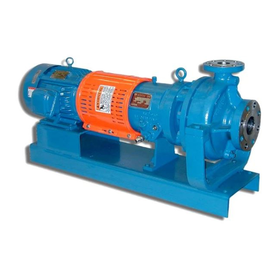
- Page 4 700 Emlen Way, Telford, PA 18969 USA Phone: 215.723.8155, Fax: 215-723-2197, Toll Free: 800-392-7621 Email: infofhs@onececo.com • Website: cecoenviro.com ST ND RD, HORIZONT L, SINGLE ST GE, END SUCTION, ENCLOSED IMPELLER, CENTRIFUG L PROCESS PUMPS TYPES R5140, R5170, R5180 ND R5240 MECH NIC L DESIGN SPECIFIC TIONS T ND RD TERI LS OF...
- Page 5 INST LL TION lways wear the appropriate protective apparel when working on B SEPL TE MOUNTING ND LIGNMENT or around the pumping equipment. Safety glasses with side shields, The sequence of mounting which must be observed for proper base- heavy work gloves (use insulated work gloves when handling hot plate and pump mounting is: items), steel-toed shoes, hard hat, and any other protective gear as 1) Place baseplate, with pump and driver mounted thereon, on the...
- Page 6 may have forced the pump out of alignment. If so, correct the of the pump shaft when the unit is running. lthough pumps and piping to remove the distorting load, and realign the pump drivers are check aligned at the factory, this is only to confirm that and driver.
- Page 7 To check the offset alignment, mount the dial indicator as above On the R440 series pumps, moderate alignment adjustments may except with the indicator button on an outside diameter of the sta- be made by using the jack bolts provided on the bearing housing tionary coupling hub.
- Page 8 PUMP COOLING REQUIREMENTS Pumps may be furnished with the following jackets or cooling coil: COOLING W TER PIPING The cooling water piping depends on what cooling coil or jackets 1) Stuffing box are furnished and used. Jackets to be piped in series are, Casing 2) Mechanical seal gland (optional) Pedestal Cooling, Stuffing Box Cooling, and Bearing Housing Cooling, with the cooling water to flow in that sequence.
- Page 9 PIPING CONNECTIONS FOR R5000 SERIES PUMPS Connections (1) and (3) are cooling water inlets. Connections (2) sealed with standard, metal, threaded pipe plugs at the manufactur- and (4) are cooling water outlets. Do not control cooling water flow ing plant. with a valve on connections (1) and/or (3).
- Page 10 PUMP LUBRIC TION Lubrication of the ball type bearings in Dean pumps is by oil Invert the glass reservoir, so that the bias cut tube is pointing contained in the sump of the bearing housing (26). The oil must upward, and fill it with oil through this tube. Screw the glass be a good grade of rust and oxidation inhibited, non-foaming, reservoir back into the body of the utomatic Oiler.
- Page 11 ST RTING THE PUMP It is important that a pump should never be subjected to thermal or change the wiring connections and recheck rotation. Operating the pressure shock. The liquid should therefore be allowed to flow into pump in reverse rotation may cause extensive damage. the casing slowly.
- Page 12 PUMP ST RT UP CHECK LIST These points must be checked after pump installation and before er. If not, connect the wiring for proper rotation and recheck. starting up the pump. 7) Check coupling for proper alignment. Realign if neces sary. 1) Read instruction manual thoroughly and understand it.
- Page 13 PUMP DESIGN TION CODE FOR R4140 R4142 Pump with jacketed seal chamber - R4144 UMP WITH CKETED H MBER E RING OUSING OOLER R4144 Pump with jacketed seal chamber and oil cooler R4146 Pump with large taper bore seal chamber R4147 Pump with jacketed seal chamber and jacketed casing...
- Page 14 R4140 DIS SSEMBLY ND SSEMBLY PROCEDURES W RNING: from the pump. Hook a lifting hoist to the lifting eye(s) of the Work must be performed only by thoroughly trained and qualified motor and take the slack out of the cable or chain. Make sure that all of the components of the lifting apparatus are capable personnel to assure quality repair and to reduce the possibilities of injury to personnel and/or damage to equipment.
- Page 15 allowing liquid to flow from the system into the pump. Personal a) Remove gland stud nuts (15) and slide gland (13) away from injury, death and/or equipment damage may occur if great caution seal chamber. is not exercised. b) Remove packing from stuffing box if pump is packed. Use pack- n) Because of the above possibility, when you loosen the gasketed ing extractor.
- Page 16 weld from between the ring and the casing before prying out will be inline with the machined “oil return” slot in the end the ring. cover (28). k) Press the bearings (25 and 25 ) onto the pump shaft (29). q) If necessary, remove the casing back cover ring (6) by prying it Press only on the inner races of the bearings.
- Page 17 the labyrinth (76) must be positioned so that it is towards the bot- HRUST E RINGS tom of the bearing housing (26) q) Dean pumps are made with a lapped metal-to-metal joint between the shaft sleeve (10) hook and the locating shoulder on the shaft (29) to prevent liquid leakage under the shaft sleeve.
- Page 18 On motor sizes 213TC and 215TC, place motor hub to over- am) Tighten the motor support (83) to bearing housing (26) bolts to hang motor shaft by 5/16”. 65 ft. lb. On motor sizes 254TC and 256TC, place motor hub flush with an) Bolt the pump assembly to the baseplate, at the motor support the end of the motor shaft.
- Page 19 R450 P - R454 UMP WITH CKETED H MBER E RING OUSING OOLER R444, R454or R484 Pump with jacketed seal chamber and oil cooler R446, R456or R486 Pump with large taper bore seal chamber and oil cooler R448, R458or R488 Pump with jacketed seal chamber, jacketed casing and oil cooler...
- Page 20 R440, R450 and R480 DIS SSEMBLY ND SSEMBLY PROCEDURES W RNING: pressure in the system when the pump was stopped; the quality, Work must be performed only by thoroughly trained and qualified type, and condition of the isolation valves; the thermal expan- personnel to assure quality repair and to reduce the possibilities of sion values of the fluid and the pump material;...
- Page 21 adhered to. The type of gasket and material of construction will g) Remove the shaft sleeve (10) and shaft sleeve key (10K) from vary with service requirements. ttack by prying and then, if the shaft. necessary, layering off the old gasket with a sharp scraper, h) Loosen set screw in splash collar (18).
- Page 22 Use only Dean Pump Division of Met-Pro Corporation parts. HRUST E RING DJUSTMENT To reassemble the pump, perform the following steps: a) Clean all parts thoroughly. b) If needed, press a new throat bushing (54) carefully into the casing backcover (22). c) If needed, press a new casing backcover ring (6) into the casing backcover (22).
- Page 23 Use a chisel to bend the side of the impeller lock washer (12B) Tighten the casing stud nuts (5C) to 105 Ft.Lb. for 3/4" studs up against a flat of the impeller bolt, approximately 90° from and 165 Ft.Lb. for 7/8" studs. the blind hole.
- Page 24 P CKING INST LL TION the bottom of the seal chamber and the lantern ring. Insert pack- These instructions apply to the conventional woven, braided, folded, ing rings as above until the lantern ring position is reached and and wrapped packings. Packings of multifilament Teflon, braided then install the lantern ring.
- Page 25 with crocus cloth. ny roughness on the shaft sleeve may damage Now tighten the gland stud nuts carefully and evenly to avoid cock- the mechanical seal shaft packing when the seal is assembled. ing the gland, making sure that the gland insert and gaskets are in place.
- Page 26 INST LL TION OF DOUBLE INSIDE UNB L NCED SE LS chamfered on the outside diameter on one end, it is necessary to To make the seal installation, with the pump partially assembled as have this chamfer facing away from the insert (315). Lubricate the noted above, scribe a mark on the shaft sleeve (10) exactly in line outside diameter of the seat rings (328), the inside of the casing with the face of the pump seal chamber.
- Page 27 One example of other gear would be breathing Use only Dean Pump Division of Met-Pro Corporation parts. apparatus when working near toxic materials. Use only top quality tools. ©COPYRIGHT 2012 CECO ENVIRONMENTAL, DE N PUMP ® IS REGISTERED TR DEM RK OF CECO ENVIRONMENTAL 09-5921 512...
Need help?
Do you have a question about the DEAN PUMP R5000 Series and is the answer not in the manual?
Questions and answers