
Subscribe to Our Youtube Channel
Related Manuals for Ceco Dean Pump M300


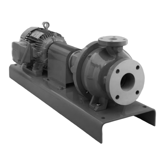
Summary of Contents for Ceco Dean Pump M300
- Page 1 M300 ® ERIES Magnetically Coupled Horizontal Process Pumps DO NOT INST LL, OPER TE, OR SERVICE THIS PUMP BEFORE RE DING THE ENTIRE M NU L Instruction Manual MC 1.3.10.2...
-
Page 2: Table Of Contents
INDEX Caution ..................3 Product Inspection and Test . -
Page 3: Caution
C UTION C UTION—THIS EQUIPMENT CONT INS BRITTLE ND This hazard also exists when holding parts with your hands M GNETIC M TERI LS. during assembly. The most common mechanical damage is chipped magnets and ruined wrist watches. Chipped magnets, if used, can cause C UTION—EXTREME H Z RD extensive mechanical damage when particles come loose during HE RT Magnets in/from this pump can upset the timing of... -
Page 4: Warning
RECEIVING PUMP warranty; (IV) any loss or damage to or defects in any Dean Products resulting from the misuse or improper storage, installa- When the pump is received from the transportation company, it tion, or operation thereof; or (V) any loss or damages to or should be promptly inspected for damage and such damage defects in any Dean Products resulting from any alteration or noted on the bill of lading before it is signed. -
Page 5: Mechanical Design Specifications
ECH NIC L ESIGN PECIFIC TIONS Frame I Frame II Frame III 1 x 1 2 x 3 x 6 2 x 3 x 8 x 3 x 10 4 x 6 x 10 x 3 x 8 2 x 3 x 10 Pump Sizes x 3 x 6 3 x 4 x 8... -
Page 6: Standard Materials Of Construction
T ND RD TERI LS OF ONSTRUCTION STM -278 Class 35 Part # Part Name Class 22 Class 50 Class 60 Impeller Cast Iron (1) 316 S/S (2) lloy 20 (3) STM -744 Grade CF8M Impeller Key 316 S/S (15) 316 S/S (15) lloy 20 STM -744 Grade CN-7M... -
Page 7: Pressure/Temperature
LLOW BLE ORKING RESSURE VS UMPING EMPER TURE... -
Page 8: Installation
INST LL TION PUMP FOUND TION Suction piping should have a minimum friction loss and thus should be as short and straight as possible with a pipe diameter The pump foundation provides rigid support to the baseplate and maintains the alignment of the pumping unit. Baseplates as large as economically feasible for the flow rate handled. -
Page 9: Baseplate Mounting And Lignment
If the pump has optional drain connections, there will be a PUMP ND DRIVER LIGNMENT drain connection in the bottom of the casing (5) and a contain- Proper running life of a pump and driver unit depends on the ment shell drain in the bottom of the casing cover (22). Do not accuracy with which the axis of the driver shaft coincides with connect these two drains together, as it would cause a “short the axis of the rotor shaft when the unit is running. -
Page 10: Grouting The Baseplate
To check the offset alignment, mount the dial indicator as NDIC TOR ETUP TO NGUL R IS LIGNMENT above except with the indicator button on an outside diameter of the stationary coupling hub. Rotate the shaft on which the dial indicator is mounted, allowing the indicator button to ride on the outside diameter of the stationary hub. -
Page 11: Llowable Piping Loads
LLOW BLE PIPING LO DS M300 SERIES PUMPS Pump Flanges Pump ∑ ∑ Forces Moments Discharge Suction Size ∑F ∑M F & M Fr & Mr 1 x 1.5 x 6 394 267 311 284 556 384 182 350 267 136 1.5 x 3 x 6 394 270 311 285 556 532 182 395 194 136 270 182 1 x 1.5 x 8 394 222 311 274 556 264 182 321... -
Page 12: Piping Connections
PIPING CONNECTIONS FOR M300 SERIES PUMPS - INTERN L... -
Page 13: External
PIPING CONNECTIONS FOR M300 SERIES PUMPS - EXTERN L... -
Page 14: Optional Protection Systems
OPTION L PROTECTION SYSTEMS The M300 series pumps incorporate the latest technology and 4) PRESSURE SWITCH. pressure switch can be mounted are expertly manufactured and assembled to provide long, to sense pressure from the 1/4" NPT frame connection trouble free operation. dditional security and safety can be or the 1/4"... -
Page 15: Starting The Pump
ST RTING THE PUMP The pump must be primed prior to start-up. containing parts and cause severe hazard to personnel and/or damage to the system. The heat will also severely damage the When the source of liquid supplied to the pump is below pump. -
Page 16: Pump Start-Up Checklist
PUMP ST RT-UP CHECKLIST These points must be checked after If the driver rotation is incorrect, pump installation and before starting up reconnect the wiring for proper the pump. rotation and re-check. 1) Read the instruction manual 9) Check the coupling for proper thoroughly and understand it. -
Page 17: Spare Parts
SP RE P RTS ORDERING SP RE P RTS To avoid prolonged down time and facilitate rapid repair of Spare part orders will be handled with a minimum delay if the damaged pump parts, Dean recommends the pump user following information is furnished by the customer with the order: maintain a minimum stock of spare parts. -
Page 18: Pump Section View
PUMP SECTION VIEW Part # Part Name Part # Part Name Part # Part Name Impeller Outboard Bearing Cover Outer Magnet ssembly Impeller Key Pump Shaft Inner Rotor Key Casing Drive Shaft Inner Magnet ssembly Casing Drain Plug Bearing Lock Nut Bearing Cartridge 9 ❍... -
Page 19: Internal Circulation Flow Path
INTERN L CIRCUL TION FLOW P TH The internal circulation flow path through the bearings and the front thrust collar (210), through the balance holes in the magnetic coupling is supplied with discharge pressure and impeller (3) back to the suction of the pump. The rest of the flow returns to discharge pressure. -
Page 20: Disassembly And Ssembly Procedures
DIS SSEMBLY ND SSEMBLY PROCEDURES W RNING: Work must be performed only by thoroughly dures and precautions as specified are adhered to. Proper attire trained and qualified personnel to assure quality repair and to shall be worn during disassembly and decontamination. reduce the possibilities of injury to personnel and/or damage Pumps requiring factory repair must not be returned or trans- to equipment. - Page 21 f) Flush each sub-system with a compatible, non-toxic, non- screws in the flange of the casing cover (22) to break the hazardous, stable liquid. Drain into individual containers gasket seal. If fluid and/or pressure remains in the pump for each fluid. Disconnect and remove all auxiliary piping. it will spray out now.
- Page 22 Use mechanical lifting equipment to lift assemblies and components. The number of rows of magnets in your pump will be shown in the paperwork for that particular pump. If you do not have that Do not apply heat to parts to assist in disassembly. Explosion information at hand, you can measure the axial length of the could occur causing personal injury, death, and/or damage to magnets in the outer magnet assembly (167) and compare it...
- Page 23 ny loose metal attracted to the magnets must be completely Remove the snap ring from the outer race of the out- board bearing (25 ). Do not remove the bearing lock removed before re-assembly; therefore, attempt to keep the surfaces as clean as possible. nut (31).
- Page 24 RE SSEMBLY PROCEDURE polished face exposed. Lubricate the polished face with a light film of light oil. Place the carbon face of the W RNING: Use only high quality tools. rotating portion of the mechanical seal against the Wear protective equipment as advised at the beginning of this section. polished face and center it.
- Page 25 safety glasses, gloves, and a long sleeved shirt during Lubricate the bearings (182), the journal sleeves (200) this operation. Care must be exercised so that the brittle and the face of the thrust collar (210) with a light oil. inner member of the casing cover wear ring assembly Slide the pump shaft (29) carefully through the bearings (195) is not broken.
- Page 26 Lay the assembly over so that the shaft is in a horizontal Install any auxiliary piping which must be affixed to the pump before it is mounted to the baseplate. position. Place a new casing gasket (77) into the casing (5) and Remove the impeller nut (12), impeller washer (12 ) and the handle, or the optional eye bolt.
- Page 27 ’ USTOMER L NT INTEN NCE ECORD Dean Pump Serial Number Plant Property Number Service Location Capacity ; T.D.H. ; Imp. Dia. ; Temp. ; RPM Spare Parts in Plant Stock Room Interchangeable with Dean Serial Numbers...
- Page 28 6040 Guion Road • Indianapolis, IN 46254 (317) 293-2930 • F X: (317) 297-7028 E-mail: infofhs@onececo.com • Web Site: www.cecoenviro.com RE D W RNINGS H Z RDOUS SITU TIONS M Y OCCUR UNLESS THIS EQUIPMENT IS PPLIED, INST LLED, OPER TED, ND M INT INED BY THOROUGHLY QU LIFIED PERSONNEL IN STRICT CCORD NCE WITH THE INSTRUCTION M NU L ND LL PPLIC BLE DR WINGS ND CODES.
Need help?
Do you have a question about the Dean Pump M300 and is the answer not in the manual?
Questions and answers