Table of Contents
Advertisement
Advertisement
Table of Contents

Related Manuals for Avery Weigh-Tronix WI-150


Summary of Contents for Avery Weigh-Tronix WI-150
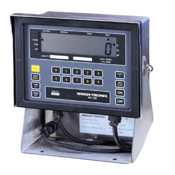
- Page 1 WI-150 Ultra Low-Power Weight Indicator Service Manual...
- Page 2 All Weigh-Tronix products bearing the Factory Mutual seal are designed and manufactured ac- cording to the guidelines set forth by Factory Mu- tual Research. It is the responsibility of the owners to gain approval from their insurance companies for the suitability of the Weigh-Tronix equipment and installation for their particular environment and use of the product.
-
Page 3: Table Of Contents
SC-150 Remote Control Parts & Assembly ..............34 SC-150 Option Board/Main Board .................. 35 SC-150 Remote Control PC Board Identification ............36 SC-150 System Block Diagram ..................37 Fiber-Link Enclosure Outling Dimensions and PC Boards ..........39 WI-150 Keypad and Schematic ..................42... -
Page 4: Introduction
Opera- tions mode is fully explained in the User's Manual . Test Mode Use this mode to perform tests on the WI-150. The test mode is covered in the User's Manual . Configuration Mode Use this mode to set up options and program the operation of the scale and indicator. -
Page 5: Sealing The Indicator
Sealing the Indicator The WI-150 can be sealed. If sealed, no configuration items can be changed in the configuration menu. Seal the unit by placing switch S1-1 in the OFF position. Unseal the unit by placing S1-1 in the ON position. Remove the front panel of the indicator to gain access to switch S1-1. - Page 6 Enters numbers and specifies tare 0 0 0 0 0 9 9 9 9 9 keypad registers and cutoff values. MENU Used to access menus and move among choices in a menu. PRINT Sends a print command and is used to select menu items. SELECT Enters a pushbutton tare in gross/net operation.
-
Page 7: Configuration Mode
The menu reflects a WI-150 model with time and date and other options installed and enabled. Your system may differ. - Page 8 Setup ↓ Scale ↓ Units → Capacity → Division → Density This option lets you set the density of the liquid you are weighing in grams per cubic centimeter. Your scale will then convert the weight of the liquid into gallons. (Specific gravity is identical to density as expressed in grams per cubic centimeter.) Setup ↓...
- Page 9 Figure 2 Configuration Menu...
- Page 10 Key: Available only when SC-150 is enabled Default values...
- Page 11 Setup ↓ Scale → Options ↓ Control → Tare → Choosing ON enables the ID number. OFF disables the ID number. If ID is disabled, ID will not appear in the SECURITY section of this menu. Setup ↓ Scale → Options ↓ Control → Tare → ID → Cutoffs ↓ Total , Ingred., Latched Total—...
- Page 12 Setup ↓ Scale → Options → Security → Serial A/B ↓ Print ↓ Button → Enquire This option is not seen on the battery-powered version of the WI-150. On the AC//DC powered version this sub-menu allows you to choose a printer or other device which will send an enquire code to the indicator.
-
Page 13: Layout
Setup ↓ Scale → Options → Security → Serial A/B ↓ Print → Busy → Baud → Parity ↓ Clear Even, Odd This option lets you choose parity as even, odd, clear (logic 0 or space), or set (logic 1 or mark). Data Bits Stop Bits Parity... -
Page 14: Customizing The Layout Menu
Figure 4 Default Layout Menu As in the other WI-150 menus, the SELECT key opens up the next level of the menu. There is one more level of information under the print commands in the layout menu. This information may be one of two types: •... - Page 15 #31- Sets IMP printer to 40 column print mode #79- #15- Makes double wide characters until a carriage #78- return #73- #14- Makes double high characters until a carriage #88- return #32- Space #87- #87- #69- #73- − #73- #45- #71- #49- #72-...
-
Page 16: Examples & Step By Step Instructions
Example A: If you want to change the second print command in Figure 4 Examples and Step by from 2 HOUR to 2 TARE, with 2 HOUR displayed, press SELECT. Now Step Instructions scroll to the TARE print command in the submenu and press SELECT to select it. - Page 17 With 1 ASCII displayed, press Deleting an ASCII print CLEAR . . . The item is removed from the menu command after the ASCII and all the following items move up codes are cleared one number value on the menu. What was item 2 becomes item 1, etc.
- Page 18 Table 2 ASCII Control Codes N O T E: To repeat a control code a number of times, enter the control code #, a decimal, then the number of times N O T E N O T E N O T E N O T E you want it repeated.
- Page 19 Setup ↓ Scale → Options → Security → Serial A → Serial B → Binary Coded Decimal which allows transmission to certain printers. This paramter appears only when the SC-150 is enabled. Setup ↓ Scale → Options → Security → Serial A → Serial B → BCD → Analog ↓ Output This lets you specify which weight the analog output will follow.
-
Page 20: Adjusting Dead Load
Adjusting Dead Load The dead load offset adjustment provides compensations to cancel out the weight of the scale platform and any permanently fixed weight supporting structures on the platform. Adjusting the dead load should be completed before calibration of the Indicator. To adjust the dead load: 1. -
Page 21: Calibration Procedures
Calibration Procedures To calibrate your WI-150, you must enter the Configuration Menu outlined below. If you are already in the Configuration Menu, go directly to the Make sure your test weights procedures for setting Zero & Span and Linearity and viewing Display which match the selected unit of are continued on the next page. -
Page 22: Setting Zero And Span
1. When ZERO is displayed, Setting ZERO and SPAN remove all weight from scale. (Calibration) Wait till the scale is stable and press SELECT. BUSY is displayed briefly, then 0 . ZERO is displayed. 2. Press SELECT again. 3. Press MENU. SPAN is displayed. -
Page 23: Reset Menu And Master Clear
Reset Menu and Master Clear If the indicator's memory, calibration or other data becomes corrupted, a reset menu will become active. RESET will be displayed telling you there has been a problem. You may also choose to perform a Master Clear to The only items active for a reset the setup, adjust or data values to default values. -
Page 24: Reset Menu
The following are instructions for moving around within the Configuration Menu: If a new microprocessor is installed in the WI-150, the COP (Com- puter Operating Properly) watchdog system will need to be reset. Do this by turning off the unit, placing a jumper between pin 1 and pin 2 of P7 and a jumper between pin 1 and pin 2 of P8. -
Page 25: Disassembly And Reassembly
Disassembly and Reassembly Follow these steps to disassemble and reassemble your WI-150 indicator. 1. Be sure the unit is not connected to a power source and remove the indicator from the stand by removing the two nuts pointed out in Figure... - Page 26 3. Pull the front panel from the back enclosure. 4. Remove any cables connected to the cards or main PC board. 5. Remove the 2 cards plugged into the main PC board by pulling them up and away from the main card. See Figure 9. Figure 9 PC board layout 6.
-
Page 28: Indicator Parts And Assembly
WI-150 AC/DC INDICATOR (BATTERY POWERED) AC/DC BARRIER POWERED, PARTS AND ASSEMBLY ITEM DESCRIPTION W-T P/N Front Panel Switch Overlay 28880-0014 Bezel 28928-0018 Stand 28919-0019 Rubber Foot 15349-0024 Flat Washer 14475-0023 Screw 14473-0116 Standoff 15457-0022 Front Panel 28892-0010 Enclosure (stainless) 28888-0016... -
Page 29: Cable To Pc Board Connection
WI-150 INDICATOR AC/DC BARRIER POWERED CABLE TO PC BOARD CONNECTION CABLE PIN-OUTS... - Page 30 WI-150 AC/DC INDICATOR (BATTERY POWERED) CABLE TO PC BOARD CONNECTION...
-
Page 31: System Block Diagram
WI-150 INDICATOR SYSTEM BLOCK DIAGRAM... -
Page 32: Pc Board Identification
Switching circuitry (U3), a dual slope ratiometric integrator (U4), a comparator (U5), analog to Digital control logic circuitry (U4), comparator (U5), analog to digital control logic circuitry (U7 & U8), And the analog circuitry voltage supply (U9 & U10). WI-150 INDICATOR MAIN PC BOARD P/N 28569-0020 Main PC Board Description The main board consists of a motorola microprocessor IC (U1), control circuitry (U2 &... - Page 33 WI-150 AC/DC INDICATOR PC BOARD IDENTIFICATION (CONTINUED) POWER SAVER PC BOARD P/N 28178-0023 Battery Powered Power Saver Board Description This board provides the control timing circuitry for the analog to digital board. It Activates the analog circuitry as needed to reduce power consumption.
-
Page 34: Bp-150 Battery Pack And Charger Parts And Assembly
BP-150 BATTERY PACK and BC-150 BATTERY CHARGER, 115/230 VAC PARTS AND ASSEMBLY BP-150 BATTERY PACK P/N 28980-0013 BC-150 BATTERY CHARGER MAIN PC BOARD P/N 28243-0016 The PC board changes the supplied AC voltage to a DC output. When connected, this DC output is used to charge a battery pack such as the WEIGH TRONIX BP-150. -
Page 35: Ps-150 Power Supply 115Vac/230Vac Parts & Assy
PS-150 POWER SUPPLY 115/230 VAC, PARTS AND ASSEMBLY POWER SUPPLY ASSEMBLY P/N 29482-xxxx (old style) POWER SUPPLY ASSEMBLY P/N 29482-xxxx (new style) ITEM ITEM DESCRIPTION W-T P/N DESCRIPTION W-T P/N Power Supply PC Board (115vac) 28237-0014 Power Supply PC Board (115vac) 28237-0014 Power Supply PC Board (230vac) 28237-0022... -
Page 36: Ps-150Xp Power Supply Main Board Parts And Assembly
PS-150XP POWER SUPPLY (115/230VAC), PS-150 MAIN PC BOARD PARTS AND ASSEMBLY PS-150XP POWER SUPPLY, P/N 48171 –0010(115V), -0028(230V) PS-150 PC BOARD, P/N 28237 –0014(115VAC), -0022(230VAC) The PS-150 PC board converts either 115vac or 230vac input to a regulated output of 13.5vdc with no load. -
Page 37: Sc-150 Remote Control Parts & Assembly
SC-150 REMOTE CONTROL PARTS AND ASSEMBLY ITEM DESCRIPTION W-T P/N Main Pc Board Assembly 28231-0036 Chassis 28925-0011 Enclosure 28924-0012 Front Panel 29330-0018 Rubber Foot 15349-0024 Rear Panel 28926-0010 Connector Blank 28941-0011 specify Fuse, ¼ A (230VAC) 15453-0067 Fuse, ½ A (115VAC) 15453-0083 Fuse holder 15455-0016... -
Page 38: Sc-150 Option Board/Main Board
SC-150 REMOTE CONTROL OPTION BOARD/MAIN BOARD... -
Page 39: Sc-150 Remote Control Pc Board Identification
SC-150 REMOTE CONTROL PC BOARD IDENTIFICATION MAIN PC BOARD ASSY, P/N 28231-0036 DUAL RS-232/RS-422/RS-485 BOARD ASSEMBLY P/N 28024-0011 CUTOFF I/O INTERFACE BOARD P/N 28228-0015 This board provides multiple low current logic controlled outputs for switching external devices on or off at pre- Programmed or operator selected levels. -
Page 40: Sc-150 System Block Diagram
SC-150 REMOTE CONTROL PC BOARD IDENTIFICATION (CONTINUED) PARALLEL OUTPUT BCD BOARD P/N 28821-0016 The Parallel BCD Output board provides latched parallel BCD data for peripheral devices such as printers or remote displays. An input is provided for a “remote print” command to a printer if a “print” command is actuated by pressing the data send key or by an external print switch. - Page 41 SC-150 REMOTE CONTROL SYSTEM BLOCK DIAGRAM...
-
Page 42: Fiber-Link Enclosure Outling Dimensions And Pc Boards
FIBER-LINK CONVERTER MODULE ENCLOSURE OUTLINE DIMENSIONS PC BOARDS RS-422 PC BOARD P/N 45788-0011 The Fiber Link RS-422 Serial Interface board allows the weight indicator to communicate via fiber optic cables with peripheral devices such as a printer, computer, or programmable controller. - Page 43 FIBER-LINK CONVERTER MODULE PC BOARDS (CONTINUED) CURRENT LOOP BOARD, RS-232 PC BOARD P/N 45785-0014 P/N 45164-0015 This Fiber-Link board is able to be configured as either a 3 or 4 wire mA The Fiber-Link Serial Interface provides a serial communication link Current loop serial communication port to a peripheral device such as a printer, between a Weigh-Tronix weight Indicator and a peripheral device such computer, or a programmable controller.
- Page 44 FIBER-LINK CONVERTER MODULE PC BOARDS (CONTINUED) ANALOG PC BOARD CUTOFF PC BOARD P/N 45833-0016 P/N 45836-0013 The analog Output Interface provides a switch selectable range of current or DC voltage to a peripheral device. The Fiber-Link Cutoff interface provides multiple, low current logic controlled outputs for switching external devices on or The output from this Fiber Link is software selectable to be proportional to the displayed weight, gross weight off at pre programmed or operator selected levels.
-
Page 45: Wi-150 Keypad And Schematic
WI-150 INDICATOR KEYPAD AND SCHEMATIC... - Page 46 Weigh-Tronix 1000 Armstrong Dr. Fairmont, MN 56031 USA Telephone: 507-238-4461 Facsimile: 507-238-4195 e-mail: industrial@weigh-tronix.com www.weigh-tronix.com Weigh-Tronix Canada, ULC 217 Brunswick Blvd. Pointe Claire, QC H9R 4R7 Canada Telephone: 514-695-0380 Facsimile: 514-695-6820 Weighing Products & Systems Weigh Bar ® is a registered trademark of Weigh-Tronix Inc. 04/13/00 150SERV.P65 PN 29535-0011e1 Printed in USA...
Need help?
Do you have a question about the WI-150 and is the answer not in the manual?
Questions and answers