
Related Manuals for Svantek SV 258PRO


Summary of Contents for Svantek SV 258PRO
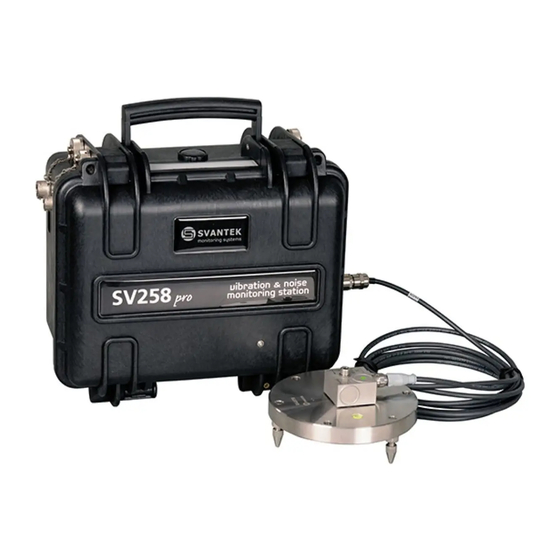
- Page 1 USER MANUAL SV 258PRO BUILDING VIBRATION & NOISE MONITORING STATION (firmware 958AG) Copyright © 2020 SVANTEK. Warsaw, 2020-08-21 Rev. 2.00 All rights reserved.
- Page 2 Information in this document is subject to change without notice and does not represent a commitment on the part of Svantek. Svantek provides this document “as is,” without warranty of any kind, either expressed or implied, including, but not limited to, its particular purpose. Svantek reserves the right to make improvements and/or changes to this manual, or to the products and/or the programs described in this manual, at any time.
-
Page 3: Important Notes Before Use
SV 258 PRO (AG) User Manual IMPORTANT NOTES BEFORE USE ✓ Only SVAN 958A and the controller can be disconnected and removed from the station case by the user. All other disassembling work should be performed strictly by an authorized service team. ✓... -
Page 4: Table Of Contents
SV 258 PRO (AG) User Manual Table of Contents: IMPORTANT NOTES BEFORE USE ................3 INTRODUCTION ....................6 Features ..........................6 Accessories included ....................... 7 Accessories available ...................... 7 MONITORING STATION SET................8 SV 258 PRO standard set and optional elements ............8 SV 258 PRO –... - Page 5 SV 258 PRO (AG) User Manual 4.2.4 Description of icons ....................29 4.2.5 Data saving ......................30 4.2.6 Files downloading and uploading ................31 Instrument configuration - Menu ................... 31 Instrument’s calibration – Calibration ............... 32 4.3.1 Selecting standard and additional measurements – Application ....... 34 4.3.2 Viewing the table for building type –...
-
Page 6: Introduction
SV 258 PRO (AG) User Manual 1 INTRODUCTION SV 258 PRO is an outdoor monitoring system based on the SVAN 958A class 1 vibration and sound four-channel level meter dedicated for ground and building vibration applications. The portable and battery powered station can be used for a variety of monitoring applications including construction site monitoring, tunnelling and blasting. -
Page 7: Accessories Included
SV 258 PRO (AG) User Manual 1.2 A CCESSORIES INCLUDED SVAN 958A Four channel Class 1 Sound & Vibration Analyser SM 258 PRO Outdoor monitoring station for SVAN 958A including: 17Ah battery, 3G modem (SP 270) and external power supply (SB 270) SC 16 USB 1.1 cable SC 61... -
Page 8: Monitoring Station Set
SV 258 PRO (AG) User Manual 2 MONITORING STATION SET 2.1 SV 258 PRO STANDARD SET AND OPTIONAL ELEMENTS The SV 258 PRO station consists of two carrying cases. The main case is waterproof with the internal 17 Ah battery and internal controller supporting powering from the dedicated external DC or solar panel. -
Page 9: 258 Pro - Waterproof Case
SV 258 PRO (AG) User Manual Additional accessories for the SV 258 PRO system, not included in the standard set, but in many applications, essential for reliable system operation and task performance are: 1. Outdoor sound measurement set (SV 208A) see Chapter 2.2.1, 2. - Page 10 SV 258 PRO (AG) User Manual Note: Only SVAN 958A and the controller can be disconnected and removed from the station case by the user. All other disassembling work should be performed strictly by an authorized service team. Note: The producer does not recommend removing the controller without a sound reason. Double check that the controller has a good fixation in the socket after reconnecting! The monitoring station case is equipped with an air pressure compensation valve that enables easily opening of the case...
-
Page 11: Sd 270(A) Pro - Controller
SV 258 PRO (AG) User Manual The station is equipped with a Lead-Acid rechargeable battery (17Ah, 12V), located in the bottom of the case. The battery can be used in any chosen position without the risk of leakage. The battery has a pressure relief valves that allows safe dispersal of any excess pressure inside the cell (VRLA). - Page 12 PC. Such data exchange is carried out via the USB Device 1.1 interface of SVAN 958A (USB socket). Note: Communication of the controller or SVAN 958A with a PC requires installation of the USB drivers on your PC. USB drivers for Svantek devices are available on http://svantek.com/support- drivers-software.html Note: Before starting upgrading be sure that your SvanPC++ software is Off! If not, please Exit it before starting any upgrading.
-
Page 13: Svan 958A - Sound And Vibration Analyser
SV 258 PRO (AG) User Manual 2.1.3 SVAN 958A – Sound and Vibration Analyser SVAN 958A is a class 1 Four-channel Sound & Vibration level meter as well as a real time 1/1 or 1/3 octave or FFT analyser and is a core of the SV 258 PRO system. -
Page 14: Sp 270 - 3G Modem
SV 258 PRO (AG) User Manual There are some important settings, which should be assured in the instrument when it is a part of the monitoring station: 1. Network Setup should be set to GPRS to enable data transmission via 3G modem (path: <Menu>... -
Page 15: 84 - Building / Ground Vibration Accelerometer
The SV 84 is a part of the SV 207B set that includes also metal mounting adapter. Note: See SA 84 Technical Specification on www.svantek.com. Note: Correct connection of the accelerometer is not signalled by the controller, therefore it is recommended to perform test measurements each time the station is turned on. -
Page 16: Optional Accessories For Sv 258 Pro
SV 258 PRO (AG) User Manual 2.2 O SV 258 PRO PTIONAL ACCESSORIES FOR 2.2.1 SV 208A – Sound measurement set The SV 208A Sound measurements set includes: Microtech Gefell Prepolarised condenser microphone (MK 255), microphone preamplifier (SV 12L), outdoor microphone kit (SA 277), desiccator (SA 270D), preamplifier cable (SC 277) and carrying case (SA 250). -
Page 17: 111 - Vibration Calibrator
SV 258 PRO (AG) User Manual 2.2.2 SV 111 – Vibration Calibrator The SV 111 Vibration Calibrator is designed for in-situ checks according to ISO 8041-1:2017. In-situ checks are intended for application in the field prior to and following a measurement or series of measurements. -
Page 18: Sb 271 - Solar Panel
SV 258 PRO (AG) User Manual Note: SB 272 is not restricted for air, surface and water transport. Classified as non-hazardous material (IATA/ICAO Special Provision A67, DOT-CFR Title 49 parts 171-189, IMDG amendment 27). Note: It is necessary to charge SB 272 after any total discharge, otherwise the battery may lose its capacity. -
Page 19: Operating The Station
SV 258 PRO (AG) User Manual 3 OPERATING THE STATION 3.1 P OWERING The SV 258 PRO monitoring station can be powered from: • internal rechargeable battery, • mains power source (SB 270); and optionally from: • external rechargeable battery (SB 272), •... -
Page 20: Modes Of Station Operation
SV 258 PRO (AG) User Manual Power from Internal battery Power supply External battery Solar panel green • red when • red when CHARGING charging; charging; • green when • green when charged charged • green if loaded • when charging, •... -
Page 21: Battery Charging Mode
SD 270A, by the LED above the TEST key. Note: USB connection between the controller and the PC can be established only if the USB driver for SVANTEK instruments had been previously installed on this PC. The USB driver can be downloaded from www.svantek.com... -
Page 22: Assembling The Station
Note: If above steps don’t result in connection with SvanNET or you wish to connect to the other server, you have to configure remote communication parameters in your SVAN 958A according to the SVAN 958A User Manual or Chapter 4.3.11. In the case of further problems consult your local distributer or SVANTEK. 3.5 A SSEMBLING THE STATION 1. - Page 23 SV 258 PRO (AG) User Manual 2. Connect the SC 278 cable to the SV 84 accelerometer. 3. Install the accelerometer on the mounting adapter and screw it with the Allen key (key is included in the accessories set). 4. Remove the protection cap from the input socket (INPUT 1-3) on the case by turning it counter-clockwise and fix it on the special holder.
-
Page 24: Switching On The Station
SV 258 PRO (AG) User Manual 8. Press <Alt>+<Start> on SVAN 958A to turn on the system. 1. The station now is ready for use. 3.6 S WITCHING ON THE STATION When the remote communication is installed, and the station is fully assembled turn on the SVAN 958A instrument. -
Page 25: Svan 958Ag User Interface
SV 258 PRO (AG) User Manual 4 SVAN 958AG USER INTERFACE The instrument is controlled manually by means of nine keys on the keypad. Using these keys, one can access all available functions and change the value of all available parameters. The parameters are placed in a system of lists and sub-lists shown on the high contrast graphic colour display. -
Page 26: Basis Of The Instruments Control
SV 258 PRO (AG) User Manual • change the active field in the result presentation modes; • activate markers no. 2 and 3. (◄ / ►) The ◄ / ► keys pressed together with <Shift> allow to: • speed up the changing of the numerical values of the parameters (i.e. the step is increased from 1 to 10 in the setting of Sensitivity);... -
Page 27: Configuration Mode
SV 258 PRO (AG) User Manual Display modes present some measurement results as well as additional information in the way of icons regarding: instrument status: memory, power, real time, etc.; measurement status: measurement elapsed time, measurement start/stop/pause, trigger, logger etc.; measurement parameters: measured result, profile number, file name, detector type, filter etc. - Page 28 SV 258 PRO (AG) User Manual You may change the numerical parameter value with a larger step (usually 10) with the ◄ / ► key pressed together with <Shift>. List of options The option list consists of different options, from which only one may be selected. The selection of the option is performed in the following way.
-
Page 29: Getting Started
SV 258 PRO (AG) User Manual 4.2.3 Getting started Turning the instrument on To switch the power on, press the <Alt> and <Start/Stop> keys simultaneously. The instrument goes through the self-test routine (in this time the manufacturer's logo and the name of the instrument is displayed) and then it enters the basic view mode. -
Page 30: Data Saving
SV 258 PRO (AG) User Manual “Internal memory” icon is displayed “note” icon is displayed when the wave when internal memory is assigned for recording is active. file saving. Icons connected with modem functionality: “no wireless” icon is displayed when “no range”... -
Page 31: Files Downloading And Uploading
SV 258 PRO (AG) User Manual You can change the file name if you press the <Save> key during the Measurement mode. You will be shift to the Logger Setup screen in which you can edit the name of the file. <Save>... -
Page 32: Instrument's Calibration - Calibration
Note: The recommended factory calibration interval is 12 months for this instrument to be confident in its continuing accuracy and compliance with the international specifications. Please contact your local Svantek distributor for further details. - Page 33 SV 258 PRO (AG) User Manual 4.3.1.1 Calibration by transducer's sensitivity - By Sensitivity Calibration by introducing the transducer’s (microphone accelerometer) individual sensitivity can be performed in the following way: 1. Select the By Sensitivity position from the Calibration x list and press <Enter>. <ENT>...
-
Page 34: Selecting Standard And Additional Measurements - Application
SV 258 PRO (AG) User Manual After calibration measurement stop, the Calibration Result and the Calibration Factor (difference between the Calibration Level and the Calibration Result, calculated in dB) is displayed. 6. Press <Enter> to save the new calibration factor or press <ESC> to reject it. - Page 35 SV 258 PRO (AG) User Manual In the Standard position you can switch off building vibration calculations by selecting Off value or switch it on by selecting the required standard: PPV, BS-7385-2, DIN-4150-3, KBFmax, 22/09/1994, 23/07/1986/1, 23/07/1986/2, IN-1226-A, IN-1226-B, IN-1226-C, IEST VC or User. ►...
-
Page 36: Viewing The Table For Building Type - Building Type Criterion
SV 258 PRO (AG) User Manual In the case Human Vibration measurements are selected you can switch off the PPV measurements choosing Off in the Standard position. In this case your SVAN 958AG will work as a Human vibration and optionally as a Sound measuring device. -
Page 37: Setting The Parameters For Whole-Body Vibration - Human Vibration
SV 258 PRO (AG) User Manual Select the lower and upper frequencies of the segment of the criterion curve, lover and upper values and include or not the lower and/or upper frequency points to the segment. Press <ENTER> to confirm edition. New segment will be added to the list of positions <ENT>... -
Page 38: Setting The Parameters For Sound Measurements - Sound
SV 258 PRO (AG) User Manual 4.3.5 Setting the parameters for sound measurements – Sound The fourth channel in the station can be used to measure noise in accordance with the requirements of class 1. The results such as LR, Leq, Lpeak, Lmax and Lmin, selected in the Results screen are recorded together with the vibration velocity and acceleration results making the correlation of sound and vibrations much easier. -
Page 39: Configuring Data Logging - Logging
SV 258 PRO (AG) User Manual The Timer function is used to programme the instrument to turn on at the desired time and perform measurements with settings made before the instrument was turned off. The timer can be switched off (Off) or switched on (Single). - Page 40 SV 258 PRO (AG) User Manual 1. records of so called time-history (TH) with measurements of velocity vibration from three channels and measurements of sound pressure from fourth channel made with Velocity Step, 2. records of so called summary results (SR) contained measurements of acceleration vibration from three channels and measurement of sound pressure from fourth channel made with Human Vibration Step 3.
-
Page 41: Configuring Events - Events
SV 258 PRO (AG) User Manual 4.3.8 Configuring events – Events SVAN 985AG generates SMS and e-mail notifications as well as visual and audible alarms. In addition to simple triggers from PPV or LEQ values, you can configure alarms from standard’s criterion curves (e.g. DIN 4150-3) or user’s criterion curves based on FFT or 1/3 octaves. - Page 42 SV 258 PRO (AG) User Manual When the criterion curve for a given type of building is used as the event trigger, the PPV and its dominant frequency is compared against the curve. If the PPV value exceeds the curve limit, the event will start. Reduction Factor defines the multiplying factor for the criterion curve and can be in the range: 0.1 ÷...
- Page 43 SV 258 PRO (AG) User Manual Event Duration defines duration of the Event from its start. For this period the instrument defines the maximum PPV values and dominant frequencies for X, Y and Z axis. Min. Break defines period of repetition of SMS and Email alarms. Lamp Alarm triggers the SP 272 LED/Buzzer alarm lamp.
-
Page 44: Configuring Presentation Views - Display
SV 258 PRO (AG) User Manual In the given example the Event has been started by the PPV of 15.2 mm/s at 6.592 Hz. The PPV value meets the condition of Reduction Factor that has been set to 0.5 as the value of 15.2 mm/s is at 50% of the L curve height at this point (the L at 6.59 Hz is around 30.5 mm/s). - Page 45 SV 258 PRO (AG) User Manual If for the User standard were selected 1/3 ACC or 1/3 VEL spectra (see Chapter 4.3.2), the new display mode becomes available which displays the PEAK, MAX, MIN and RMS spectra as well as Limit curve for 45 1/3-octave bands for central frequencies from 0.80Hz to 20kHz and three Total values with HP, Wd and DIN80 filters for =>...
- Page 46 SV 258 PRO (AG) User Manual If for the User standard were selected 1/3 ACC or 1/3 VEL spectra (see Chapter 4.3.2), the Time History view presents PEAK, MAX or RMS results, depending on the settings in the Application screen, calculated for the 375Hz sampling frequency without...
-
Page 47: Managing Files - File
SV 258 PRO (AG) User Manual Configuring display scale – Display Scale 4.3.9.2 In the Display Scale screen, you can select the Scale type in the Logger presentation mode: Linear or Logarithm with 80 dB dynamic range. ► Setup 4.3.9.3 Setting the display brightness and power saver - Screen In the Display Scale list, you can adjust the screen brightness and configure the power... - Page 48 SV 258 PRO (AG) User Manual (Logger rec.) and number of recorded results (Results rec.). Select the required file with the ◄ / ► key and press <ENTER>. The instrument will inform about successful loading. The result presentation screen will display measurement results, saved in the loaded file.
-
Page 49: Configuring The Remote Communication - Remote
SV 258 PRO (AG) User Manual The Defragmentation option is used to make the instrument’s memory space contiguous. perform defragmentation, press <ENTER> key. The instrument will require confirmation of the performed operation. In the case Yes, the instrument checks whether <ENT>... - Page 50 On (registration using Connection Request Packets), AS (periodic registration on Svantek Server Address), SMT.AS (registration on Svantek Server Address – performed each time internet connection is initialized by the modem). In the case the Data Protocol type is TCP C the Register Type position does not appear. In the case the Data Protocol type is UDP the Register Type can be switched off or on.
- Page 51 SV 258 PRO (AG) User Manual • Data Port – a port on which a communication socket will be configured for data exchange between remote host and the station. Default value is 8000. • Registration Port – a port on which a communication socket will be configured to transmit registration package (Register Mode: On) or exchange Http data (Register Mode: AS or SMT.
-
Page 52: Configuring System Parameters - System
SV 258 PRO (AG) User Manual 4.3.12 Configuring system parameters – System The System section consists positions enabling configuring the user interface and hardware components of the instrument. <ENT> 4.3.12.1 Selecting the language of the user interface – Language The Language position opens a screen in which you can select the language of the user interface. - Page 53 SV 258 PRO (AG) User Manual The required Date can be selected in a special window, which is opened with the ◄ / ► key after selecting the Date parameter. To set the correct date, select its position in the calendar with the ◄...
- Page 54 SV 258 PRO (AG) User Manual If Function is set to Alarm Pulse the Active Level and Hold Time positions appear. The Active Level parameter defines which level of the signal should be treated as a valid one, with “negative” or “positive” logic: Low or High. The Hold Time parameter defines the minimum duration of the alarm signal.
-
Page 55: Managing Setup Files - Settings
SV 258 PRO (AG) User Manual 4.3.12.11 Warnings selection – Warnings The Warnings position opens a screen in which you can switch on or off messages, to be displayed during the normal operation of the instrument. <ENT> If the Power Off parameter is switched on, the special warning is displayed in case you attempt to turn the instrument off. - Page 56 SV 258 PRO (AG) User Manual 4.3.13.2 Saving settings to the setup file – Save Settings The Save Settings position opens a screen in which you can define the setup file name and save it by pressing the <ENTER> key. <ENT>...
-
Page 57: Remote Control Via 3G Connection
Once all steps described in Chapter have been made, you can start working with the station via the remote-control system provided by SVANTEK. The easiest way to establish remote control is to create a user account for the SvanNET Web-service. -
Page 58: Sms / E-Mail Alarming
(host name, login name and password) into the SVAN 958AG configuration. For more details regarding DynDns service consult http://www.dyndns.org. The Address Server is a Svantek own initiative of providing the instrument's current internet address. In this mode, SV 258 PRO provides its current internet address to Svantek server. SvanPC++ is getting said address to be able to connect to it. -
Page 59: Sms Command Exchange
SERVICE SvanNET is an Internet service that simplifies the remote connection between PC and Svantek monitoring stations. SvanNET allows usage of all type of SIM cards with a 3G modem regardless of having a public or private IP. The connection over the SvanNET allows users to: •... - Page 60 SV 258 PRO (AG) User Manual 1. Press the <Alt>+<Start> keys on SVAN 958A to turn on the system. 2. Reset all settings in SVAN 958AG using Factory Settings option (path: <Menu> / Settings / Factory Settings) Note: Newly purchased stations have factory settings as a standard. 3.
- Page 61 Before logging, select your language clicking on the appropriate flag. Once logged in you can use the web interface to manage the monitoring station. Note: Ask your local SVANTEK distributer to create the SvanNET account for you and assign your new station to your SvanNET account.
-
Page 62: Svannet User Interface
SV 258 PRO (AG) User Manual SVANNET USER INTERFACE The SvanNET interface depends on the package of tools assigned to your account and access level and includes: – projects tools (Project list) – individual stations tools (Station list). Normally the extended SvanNET package requires special account permissions, but for the users of SV 258 both tools are available. - Page 63 SV 258 PRO (AG) User Manual 3. Export the view to the Word or PDF file and extend the view at the full screen. 4. Select measurement points. 5. Click the measurement point on the map to pop up three boxes with point information, current LAeq result.
- Page 64 SV 258 PRO (AG) User Manual 2. Point the cursor on the desired time point on the time-history plot to readout LAeq results for the measurement point in the right-hand area. The EVENT LIST tab displays the list of events registered within the selected period. In this tab you can: 1.
- Page 65 SV 258 PRO (AG) User Manual 2. Switch between Single events and Multi-point events. Multi-point event means the event when at least two single-point events were superimposed. 3. Scroll evnet records, which include: Date/time of the event, Event type, measurement Point, event Values (PPV and dominant frequency for the axes), Weekdays and Hours of monitoring and event Parameters (standard and duration).
- Page 66 SV 258 PRO (AG) User Manual First two plots cover all events: 1. The upper one presents PPV (Velocity) for all axes vs Dominant frequency (Frequency) in relation with the criterion curves. 2. The plot below presents time-history of peaks (Velocity). You can click the required peak to readout values of PPV for this moment.Other plots below display waveform and FFT spectrum for X, Y and Z axis for the selected event in the list.
-
Page 67: Station List View
SV 258 PRO (AG) User Manual 6.2 S TATION LIST VIEW Station list displays all stations assigned to your account – turned on and off. When you click the station, it becomes active and the tools at the right panel will be dedicated to this particular station. The station bar except station name with serial number includes five icons that indicate station state. - Page 68 SV 258 PRO (AG) User Manual If you click the station name, station information will be displayed. If you click the icon, this icon status information will be displayed: Alert status: blue - everything is OK, red – unregular event is happening. Station connection status: green –...
-
Page 69: Status View
SV 258 PRO (AG) User Manual 6.2.1 STATUS view In the STATUS view you can check the station status and configure status alarms. • To update instrument’s status, click the UPDATE STATUS button. • To configure status alarms Conditions and related Actions for the measurement points, click the STATIONS ALARMS button. - Page 70 SV 258 PRO (AG) User Manual 2. click OK and new condition will be displayed in the CONDITIONS area. The SvanNET alarms have next meanings: • Mains Trigger Value: Off – alarm is generated when the system detects loss of power supply Trigger Value: On –...
-
Page 71: Log Views
SV 258 PRO (AG) User Manual Instrument action: Set instrument clock to server time (based on owner’s time zone) – measurement is stopped, instrument clock is set (based on owner’s time zone), measurement is resumed • Station is disconnected Trigger value: xx minutes / xx hours – alarm is generated when the station remains disconnected from SvanNET for a time equal to the selected value. - Page 72 SV 258 PRO (AG) User Manual • Data Connection log which registers history of station connections. In the upper line you can: refresh the log, select the required period of records to be displayed and rewind records. • Data transfer log which registers history of data transfers (uploads). In the upper line you can: refresh the log, select the required period of records to be displayed and select the period for data transfer presentation: Monthly, Weekly, Daily or Hourly.
-
Page 73: Web Interface View
SV 258 PRO (AG) User Manual WEB INTERFACE VIEW The WEB INTERFACE view is available for the stations connected to SvanNET and enables: measurement results viewing, station parameters configuring, data files downloading and measurements start/stop. The VIEW button switches you to the Live data view (see Chapter 6.3.1) in which you can view broadband results, time-history results and event presentation. -
Page 74: Configuration Views
SV 258 PRO (AG) User Manual 6.3.2 Configuration views The Configuration view consists of several tabs that enable configuring measurement parameters (MEASUREMENT SETUP), saving measurement results (STORAGE), and triggering alarms based on events (EVENT TRIGGER). To send new configuration to the station, click the button. - Page 75 SV 258 PRO (AG) User Manual The User standard allows you to: 1. Use specific type of Spectrum: FFT Velocity, 1/3 Octave Acceleration or 1/3 Octave Velocity and Result of 1/3-octave band: Peak, Max, Min or RMS. 2. Create your own criterion curves. To create a criterion curve, select one of three curves (Curve 1, Curve 2 or Curve 3) and click +Add to add a segment of the curve.
- Page 76 SV 258 PRO (AG) User Manual As was said in Chapter 4.3.7, measurements that the instrument performs can be divided into three categories: 1. Velocity vibration measured in the first three channels by the SV 207B set. 2. Acceleration (whole-body) vibration measured in the first three channels by the SV 207B set for the. 3.
- Page 77 SV 258 PRO (AG) User Manual 5. Select sound measurement results to be saved in the file for three profiles (Leq, Lpeak, Lmax and Lmin) 6. Select statistical levels to be saved in the file (Statistical levels). Note: All measurement results and waveform are saved in the files with automatically defined names.
- Page 78 SV 258 PRO (AG) User Manual To add new event, click + Add event. New Event with CONDITIONS and Actions fields will appear. To edit the event name, click After editing the event name confirm it clicking or reject it clicking To hide the event, click Configuring conditions...
- Page 79 SV 258 PRO (AG) User Manual Select in the Source list the result which will be compared with the threshold level: PPV, RMS, LEQ, rolling RRMS and RLEQ or Curve. Selected result defines the threshold type – next parameter in this box. For LEQ the Threshold in dB should be defined in the range 20dB ÷...
- Page 80 SV 258 PRO (AG) User Manual In case of the User standard and 1/3-octave spectrum (Octave 1/3 Vel. or Octave 1/3 Acc.) if Curve is selected as a Source, two additional positions Condition 1 and Condition 2 appear. These positions allow you to set additional conditions that must be met to trigger an event which is based on comparing the RMS values from two selected profiles.
- Page 81 SV 258 PRO (AG) User Manual After occurrence of the event, actions will be performed during the time the event is active, at its beginning or at the end depending on the action type. The Alarm lamp action starts an alarm signal at the EXTERNAL INTERFACE connector to which some alarm device can be connected (for example, SP 272 alarm lamp).
-
Page 82: Status View
SV 258 PRO (AG) User Manual Address book The ADDRESS BOOK pop-up window appears in the SMS and E-mail alarm actions pop-up windows when you click the field. In this case you should select the required address (+) and click OK. You can add the contact by clicking the field. -
Page 83: Data Files View
SV 258 PRO (AG) User Manual 6.3.4 DATA FILES view The file storage window presents a list of files saved in the instrument’s SD-card memory. The list includes only files from a single directory on the memory card and it initially shows the content of the current working directory. In the Storage window, you can: 1. -
Page 84: 258 Pro Monitoring Station Technical Data
SV 258 PRO (AG) User Manual SV 258 PRO MONITORING STATION TECHNICAL DATA Parameter Value/ Description Physical data SM 258 PRO – 300 x 260 x 190 mm Dimensions SA 250 – 450 x 400 x 155 mm SM 258 PRO – ~10 kg Weight SA 250 –... - Page 85 Note: Size and power of the panel depend on the climate of the area where the station operates. Measurement Line SVAN 958A Manual and data specification are available at http://www.svantek.com Meter/analyser SV 84 accelerometer Triaxial accelerometer with sensitivity1000 mV/g. Specification is available http://www.svantek.com Microtech Gefell pre-polarised 1/2”...
- Page 86 SV 258 PRO (AG) User Manual features Five Bands UMTS (WCDMA/FDD): 800, 850, 900, 1900 and 2100 MHz 3G modem HSDPA Cat.8 / HSUPA Cat.6 data rates specifications DL: max. 7.2 Mbps, UL: max. 5.76 Mbps EDGE Class 12 data rates DL: max.
-
Page 87: List Of Related Documents
SV 258 PRO (AG) User Manual LIST OF RELATED DOCUMENTS 1. SvanNET User Manual (www.svantek.com) 2. SvanPC++ User Manual (www.svantek.com) 3. SV 84 Specification (www.svantek.com) 4. GeMalto® EHS6 Terminal User Manual (www.gemalto.com) 5. SA 277 Assembly Guide (www.svantek.com)
Need help?
Do you have a question about the SV 258PRO and is the answer not in the manual?
Questions and answers