Table of Contents
Advertisement
Advertisement
Table of Contents

Related Manuals for NSR Marine NGR-1000


Summary of Contents for NSR Marine NGR-1000
- Page 1 USER MANUAL GNSS equipment NGR-1000/NGR-3000 NGR-1000/NGR-3000 UM.E 20190331-04...
- Page 2 NOTICE TO USERS Thanks for your purchasing this product NGR-1000/NGR-3000 GNSS equipment. The copyright of this manual is owned by the manufacturer, NEW SUNRISE CO., LTD (NSR). Prior written permission is required for copying or reproducing the manual or part of the manual.
- Page 3 Modify Record Modify by Date Paragraph Version Reason 2017/06/14 First edition 2017/08/15 Add navigation function 2017/09/29 Generally modified 2019/03/31 Software update NGR-1000/NGR-3000 UM.E 20190331-04...
- Page 4 Don’t open the equipment unless you have fully understood the structure and circuits of the equipment. Only qualified personnel should work inside the equipment. Don’t disassemble or try to modify the equipment. Dangerous Turn off the power at power distribution board before installation. NGR-1000/NGR-3000 UM.E 20190331-04...
-
Page 5: Table Of Contents
5. MENU SETTING......................21 5.1 GNSS S ......................21 ETTING 5.1.1 GNSS Mode ...................... 21 5.1.2 2D/3D ........................ 21 5.1.3 Geodetic Datum ....................22 5.1.4 RAIM ......................... 22 5.1.4.1 RAIM ......................22 5.1.4.2 RAIM Level ....................23 NGR-1000/NGR-3000 UM.E 20190331-04... - Page 6 7.4.1 Sentence Setting ..................... 34 7.4.2 Baud Rate Setting ..................36 APPENDIX I MENU TREE ....................37 APPENDIX II TECHNICAL SPECIFICATIONS ............... 39 APPENDIX III SENTENCE DISCRIPTION ..............41 APPENDIX IV INSTALLATION DRAWINGS ..............57 APPENDIX V DOC ......................64 NGR-1000/NGR-3000 UM.E 20190331-04...
-
Page 7: Product Features
• 7 inch, color LCD, touch screen operation with adjustable brightness. • 3 GNSS data outputs, INS input/output. • A DGNSS beacon receiver (external) may be connected to NGR-1000/NGR-3000 to add DGNSS function. The product meets the requirements of relative IMO and IEC regulation & standards, including IMO MSC112 (73), IEC61108-1, etc. -
Page 8: Operational Overview
NGR-1000/NGR-3000 USER MANUAL 2. OPERATIONAL OVERVIEW 2.1 Control Description The GNSS equipment can by operated by key & knob on panel or touch-screen. When operated with knob, turn the knob to select an item on screen and press the knob to confirm the selection. - Page 9 NGR-1000/NGR-3000 USER MANUAL NGR-1000/NGR-3000 takes about 120 seconds to find position when turned on for the very first time. Thereafter, it takes about 15 seconds to find position each time the power is turned on. After fixed, the accurate position (in latitude and longitude) appears on the display.
-
Page 10: Turn On And Off The Power
NGR-1000/NGR-3000 USER MANUAL 2.2 Turn on and off the power Turn on the power Press the PWR button to turn on the power. Usually it will take about 2 minutes to find its position when turned on for the very first time. -
Page 11: Basic Menu Operation
NGR-1000/NGR-3000 USER MANUAL Note: When the power is turned off, the last status of brightness is stored. Therefore, when the power is turned on next time, the screen will display with the last brightness before powered off. 2.4 Basic Menu Operation Most operations of your unit are carried out through the menu. -
Page 12: Display Modes
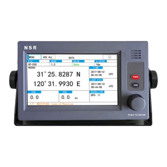
⑤ ③ Basic data will be displayed in this mode, including position in latitude and longitude, course, speed, date and time. NGR-1000/NGR-3000 takes about 120 seconds to find position when turned on for the very first time. NGR-1000/NGR-3000 UM.E 20190331-04... -
Page 13: Plotter Display
NGR-1000/NGR-3000 USER MANUAL Thereafter it takes about 15 seconds to find position each time the power is turned on. After fixed, the accurate position (in latitude and longitude) appears on the display. If position could not be found, loss of position will appear at alarm column. - Page 14 NGR-1000/NGR-3000 USER MANUAL You may increase or decrease the display range on the Plotter display. The range in the Plotter display is available among 0.02, 0.05, 0.1, 0.2, 0.5, 1, 2, 5, 10, 20, 40, 80, 160 and 320 nautical miles.
-
Page 15: Highway Display
NGR-1000/NGR-3000 USER MANUAL 2.6.3 Highway display The Highway display provides a 3-D view of own ship’s route toward destination. Navigation data is also shown. 2.6.4 Compass display The Compass display provides course with ship’s speed, and position. NGR-1000/NGR-3000 UM.E 20190331-04... -
Page 16: Satellite Display
NGR-1000/NGR-3000 can automatically advance to the next waypoint on a route, so you do not have to change the destination waypoint repeatedly. NGR-1000/NGR-3000 can store 30 routes and each route may include up to 100 waypoints. There are two ways to enter Waypoint and Route. -
Page 17: Register Waypoints
NGR-1000/NGR-3000 USER MANUAL 3.1 Register Waypoints Click NAVIGATION in SETTINGS to open the list. 1) Click to select the waypoint desired. 2) Select ADD,DELETE or EDIT desired. 3.1.1 Insert a new Waypoint NGR-1000/NGR-3000 UM.E 20190331-04... -
Page 18: Edit A Waypoint
NGR-1000/NGR-3000 USER MANUAL Create a new waypoint with the position as own ship’s current position. The new waypoint will be inserted before the waypoint which is selected by the current cursor. 3.1.2 Edit a Waypoint Edit the selected waypoint. 1) Click EDIT to edit the contents of the waypoint. -
Page 19: Delete A Waypoint
NGR-1000/NGR-3000 USER MANUAL 3.1.3 Delete a Waypoint Delete the selected waypoint. 3.2 Route Planning 1) Click to select route desired. 2) Click EDIT, FORWARD, REVERSE, ADD, DELETE, PAGE or PAGE desired. NGR-1000/NGR-3000 UM.E 20190331-04... -
Page 20: Edit A Route
NGR-1000/NGR-3000 USER MANUAL 3.2.1 Edit a Route 1) Click to select a route in ROUTE LIST desired. 2) Click the EDIT to edit the route. 3) Select ADD, RENAME, DELETE, NEXT or PREV to add, rename, or delete a waypoint in the route. -
Page 21: Forward Navigation
NGR-1000/NGR-3000 USER MANUAL Click the DELETE to delete the selected waypoint from the route. 3.2.2 Forward navigation Click the FORWARD in MENU to start navigation forward. The screen will switch to plotter page. 3.2.3 Reverse navigation Click the REVERSE to start navigation reversely. The screen will switch to plotter page. -
Page 22: Delete A Route
NGR-1000/NGR-3000 USER MANUAL 3.2.5 Delete a Route Click the DELETE to delete the selected route from route list. 3.3 Stop the Navigation by the current Route Click STOP to stop the navigation by the current route. The route is cleared on the Plotter display. -
Page 23: Alarm
NGR-1000/NGR-3000 USER MANUAL 4. ALARM Select [NOTICE SETTING] in [NAVIGATION] to open the menu. 4.1 XTE (Cross Track Error) Alarm The XTE alarm warns you by an internal buzzer when own ship is off its intended route. NGR-1000/NGR-3000 UM.E 20190331-04... -
Page 24: Speed Alarm
NGR-1000/NGR-3000 USER MANUAL Click the value field to edit. Click the digits among 0-9 desired until the desired digit is got. When the value is set to 0, XTE alarm will close. 4.2 Speed Alarm The speed alarm is activated when ship’s speed is higher (or lower) than the set value. - Page 25 NGR-1000/NGR-3000 USER MANUAL Arrival Alarm The arrival alarm informs you that own ship is approaching a destination waypoint. The area that defines an arrival zone is that of a circle which you approach from the outside of the circle. The alarm will be activated if own ship enters the circle.
-
Page 26: Track Record
NGR-1000/NGR-3000 USER MANUAL Before setting the anchor watch alarm, set current position as destination. 1) Select ANC (anchor) from ARV/ANC/OFF. 2) Click the ALARM value to edit. 3) Click the digits among 0-9 until the desired digit is got. 4) Turn the knob to move the cursor to the next digit to edit. -
Page 27: Menu Setting
NGR-1000/NGR-3000 USER MANUAL 5. MENU SETTING 5.1 GNSS Setting 5.1.1 GNSS Mode Total five modes can be selected: GPS & BEIDOU, GPS & GLONASS, GPS, BEIDOU, GLONASS. 5.1.2 2D/3D Select 2D or 3D fix mode. NGR-1000/NGR-3000 UM.E 20190331-04... -
Page 28: Geodetic Datum
NGR-1000/NGR-3000 USER MANUAL 5.1.3 Geodetic Datum Totally there are three systems to be selected: WGS84, PZ-90, CGCS2000. 5.1.4 RAIM 5.1.4.1 RAIM RAIM (Receiver Autonomous Integrity Monitoring) can be set ON or OFF. When set ON, RAIM will display SAFE, UNSAFE or CAUTION in below conditions: ... -
Page 29: Raim Level
NGR-1000/NGR-3000 USER MANUAL – the probability of false alarms >5 %, or – the probability of not detecting an error condition >5 %. Those conditions may occur if an insufficient number of satellites are available, for example 4 or 5 with 2 satellites "close" together in azimuth and elevation, causing the geometry to degrade to the point that the RAIM calculation becomes unreliable. -
Page 30: Smoothing
NGR-1000/NGR-3000 USER MANUAL 5.1.6 SMOOTHING Change the time of the COG and SOG averages to adjust the smoothness. 5.2 System Setting 5.2.1 Key Buzzer Buzzer can be muted so that operation is not heard. 5.2.2 LCD/KEY Dimmer Dimmer can be adjusted either by DIM button or set in menu. - Page 31 NGR-1000/NGR-3000 USER MANUAL 5.2.3 Day/Night Click the icon at upper right corner to change the display between day mode and night mode. 5.2.4 Time Mode Time can be set as UTC or LMT in TIME MODE. 5.2.5 Time Zone NGR-1000/NGR-3000 UM.E 20190331-04...
-
Page 32: Alert Setting
NGR-1000/NGR-3000 USER MANUAL 5.2.6 Position Offset Position may be offset with latitude and longitude. 5.3 Alert Setting When an error occurs, an alert will display on the current screen. The meanings of the alert are stated as below: When one of below three conditions met, an audible alert will be generated: - GPS not fixed. -
Page 33: Alert List
NGR-1000/NGR-3000 USER MANUAL 5.3.1 Alert List It’s to check current alert events. 5.3.2 Alarm Period Alarm period can be set between 1-5 minutes. When an alert occurs, a warning will be displayed at the bottom of screen and can be heard as a warning tone. -
Page 34: Alarm Buzzer
NGR-1000/NGR-3000 USER MANUAL 5.3.4 Alarm Buzzer Alarm buzzer can be set by clicking [ON] and [OFF]. It controls the sound of alarms. NGR-1000/NGR-3000 UM.E 20190331-04... -
Page 35: Maintenance & Diagnostics
NGR-1000/NGR-3000 USER MANUAL 6. MAINTENANCE & DIAGNOSTICS 6.1 Maintenance Check the following points regularly to maintain performance: Check that connectors on the rear panel are firmly tightened and free of rust. Check that the ground system is free of rust and the ground wire is tightly fastened. -
Page 36: Lcd Test
NGR-1000/NGR-3000 USER MANUAL 6.2.2 LCD Test LCD Test is used for testing the screen. 6.2.3 Key Test It is to test the buttons/keys on panel. NGR-1000/NGR-3000 UM.E 20190331-04... -
Page 37: Factory Default
NGR-1000/NGR-3000 USER MANUAL 6.2.4 Factory Default FACTORY DEFAULT is to return the system to factory default setting. Select FACTORY DEFAULT item in DIAGNOSTICS menu, then click [YES]. NOTE: The navigation settings and GPS settings will restore to factory default while the waypoints and routes registered remain unchanged. -
Page 38: Installation
NGR-1000/NGR-3000 USER MANUAL 7. INSTALLATION 7.1 Installation of Main Unit The main unit can be installed on a table-top, on the overhead, or in a panel (optional flush mounting brackets required). Refer to the outline drawings at the end of this manual for installation instructions. -
Page 39: Cabling
NGR-1000/NGR-3000 USER MANUAL 7.3 Cabling 7.3.1 Power Connection PIN NO DESCRIPTION PWR (+ 24V) PWR (0V) The power cable with a rated capacity of 3A should be used. Pin definition for the connector is showed above. Suggest using the 3A DC Power Supply Unit (DC 24V output). -
Page 40: Initial Setting
NGR-1000/NGR-3000 USER MANUAL 7.4 Initial Setting This equipment can output navigation data to external equipment, in NMEA 0183 format. For example, it can output position data to a radar or echo sounder. Password is required to enter “Maintenance”. For each GPS data output, following items can be configurated. - Page 41 NGR-1000/NGR-3000 USER MANUAL Data sentence description ACN: Equipment is operating normally, or for supervision of a connection between two units. ALC: Cyclic alert list. The cyclic alert list transmission shall never stop. When all alerts are in normal state the cyclic alert list is empty i.e. number of alert entries is 0.
-
Page 42: Baud Rate Setting
NGR-1000/NGR-3000 USER MANUAL GSA: GNSS receiver operating mode, satellites used in the navigation solution reported by the GGA 2148 or GNS sentences, and DOP values. RTE:Waypoint identifiers, listed in order with starting waypoint first, for the identified route. BWC:Bearing and distance to waypoint – Great circle RMB:Recommended minimum navigation information... -
Page 43: Appendix I Menu Tree
NGR-1000/NGR-3000 USER MANUAL APPENDIX I MENU TREE NGR-1000/NGR-3000 UM.E 20190331-04... - Page 44 NGR-1000/NGR-3000 USER MANUAL NGR-1000/NGR-3000 UM.E 20190331-04...
-
Page 45: Appendix Ii Technical Specifications
NGR-1000/NGR-3000 USER MANUAL TECHNICAL SPECIFICATIONS APPENDIX II GNSS equipment Item Description Receiving System GPS, Beidou, Glonass Rx Frequency 1575.42 MHz(GPS) Rx Code C/A code less than 10m (GPS), less than 5m(DGPS), 95% Position Accuracy of the time, horizontal dilution of position (HDOP) - Page 46 NGR-1000/NGR-3000 USER MANUAL INPUT/OUTPUT DATA Item Description NMEA0183, totally ports, baud rate GNSS Output 4800/9600/19200/38400 bps NMEA1.5, NMEA2.0, NMEA2.3, IEC61162 Ed4, Version IEC61162 Ed5 ALF, DTM, GBS, GNS, GGA, GSA, RMC, VTG, ZDA, Sentences etc. Beacon In DGPS RTCM 10402.3...
-
Page 47: Appendix Iii Sentence Discription
NGR-1000/NGR-3000 USER MANUAL APPENDIX III SENTENCE DISCRIPTION NGR-1000/NGR-3000 UM.E 20190331-04... - Page 48 NGR-1000/NGR-3000 USER MANUAL ACN – Alert command $--ACN,hhmmss.ss,aaa,x.x,x.x,c,a*hh <CR><LF> | +--------------------------------- 6 +---------------------------- 5 +-------------------------- 4 +------------------------- 3 +----------------------- 2 +---------------------------- 1 1. Time (see Note 1) 2. Manufacturer mnemonic code (see Note 2) 3. Alert Identifier (see Note 3) 4.
- Page 49 NGR-1000/NGR-3000 USER MANUAL ALC - Cyclic alert list $--ALC, xx, xx, xx, x.x, aaa, x.x, x.x, x.x, .., aaa, x.x, x.x, x.x*hh <CR><LF> +---------------+----------- 7 +--+-------------------------- 6 +-----+----+---+------------------------------ 5 +---------------------------------------------- 4 +--------------------------------------------- 3 +------------------------------------------- 2 +------------------------------------------ 1 1. Total number of sentences for this message, 01 to 99 (see Note 1) 2.
- Page 50 NGR-1000/NGR-3000 USER MANUAL ALF - Alert sentence $--ALF, x, x,x,hhmmss.ss,a,a,a,aaa,x.x,x.x,x.x,x,c---c*hh <CR><LF> | | | | | | | | | | | | | | | | +------------------------ 13 | | | | | | | | +------------------------ 12 | | | |...
- Page 51 NGR-1000/NGR-3000 USER MANUAL does not ignore this field it should support all alternatives defined in Table 5 Field type summary. NOTE 4: The alert category is in compliance with the category definition as described in INS Performance Standard (MSC.252(83)) and Bridge Alert Management Performance Standard (MSC.302(87)):...
- Page 52 NGR-1000/NGR-3000 USER MANUAL ‘normal’ state is reached). It can be also a null field, when there is only one alert of that type. NOTE 10: The revision counter is the main method to follow up-to-date status. Revision counter is also unique for each instance of alert. Revision counter starts with 1 and the step for increment is 1.
- Page 53 NGR-1000/NGR-3000 USER MANUAL DTM - Datum reference $--DTM,ccc,a,x.x,a,x.x,a,x.x,ccc*hh<CR><LF> | | | | | | | | +--- 7 | | | | +------ 6 | | | +---------- 5 | +--+------------- 4 | | +---+------------------- 3 | +------------------------- 2 +---------------------------- 1 1.
- Page 54 NGR-1000/NGR-3000 USER MANUAL GBS– GNSS satellite fault detection $--GBS, hhmmss.ss, x.x, x.x, x.x, xx, x.x, x.x, x.x, h, h *hh <CR><LF> +--------------------------- 8 +------------------------- 7 +--------------------------- 6 +------------------------- 5 +------------------------ 4 +----------------------- 3 +--------------------- 2 +---------------------------- 1 1. UTC time of the GGA or GNS fix associated with this sentence 2.
- Page 55 NGR-1000/NGR-3000 USER MANUAL GNS - GNSS fix data $-- GNS, hhmmss.ss, llll.ll, a, yyyyy.yy, a, c--c,xx,x.x,x.x,x.x,x.x,x.x,a *hh<CR><LF> +--------- 6 +---------- 5 +------------- 4 +----------+------------- 3 +-- +-------------------- 2 +---------------------------- 1 1. UTC of position 2. Latitude, N/S 3. Longitude, E/W 4.
- Page 56 NGR-1000/NGR-3000 USER MANUAL GGA -Global positioning system fix data $--GGA,hhmmss.ss,llll.lll,a,yyyyy.yyy,a,x,xx,x.x,x.x,M,x.x,M,x.x,xxxx*hh<CR><LF> | | | | | | | | +--------------- 11 | | | | +------------------ 10 | | | | | +--------------------- 9 | | | | | +---+--------------------- 8...
- Page 57 NGR-1000/NGR-3000 USER MANUAL GSA - GNSS DOP and active satellites $--GSA,a,x,xx,xx,xx,xx,xx,xx,xx,xx,xx,xx,xx,xx,x.x,x.x,x.x,h*hh<CR><LF> | | | | | | +----------------- 6 | | | | +--------------------- 5 | | | +------------------ 4 | | +-------------------------------------------+------- 3 | +-------------------------------------- 2 +--------------------------------- 1 1. M = manual, forced to operate in 2D or 3D mode 2165 A = automatic, allowed to automatically switch 2D/3D 2.
- Page 58 NGR-1000/NGR-3000 USER MANUAL HBT – Heartbeat supervision sentence $--HBT, x.x, A, x*hh<cr><lf> | +----------------------- 3 +------------------- 2 +------------------- 1 1. Configured repeat interval (see Note 1) 2. Equipment status (see Note 2) 3. Sequential sentence identifier (see Note 3) NOTE 1: Configured autonomous repeat interval in seconds. This field should be set to NULL in response to a query if this feature is supported.
- Page 59 NGR-1000/NGR-3000 USER MANUAL RMC- Recommended minimum specific GPS/TRANSIT data $--RMC,hhmmss.ss,A,llll.ll,a,yyyyy.yyy,a,x.x,x.x,xxxxxx,x.x,a,a,a*hh<CR><LF> | | | | | +-------------------- 9 +--+------------------ 8 +-------------------------- 7 +---------------------------- 6 +---------------------------- 5 +------+--------------------------- 4 | +-- -+-------------------------------------- 3 +---------------------------------------- 2 +-------------------------------------------- 1 1. UTC of position fix 2.
- Page 60 NGR-1000/NGR-3000 USER MANUAL NOTE 4 :The navigational status indicator is according to IEC 61108 requirements on ‘Navigational (or Failure) warnings and status indications’. This field should not be a NULL field and the character should take one of the following values: S = Safe.
- Page 61 NGR-1000/NGR-3000 USER MANUAL VTG - Course over ground and ground speed $--VTG,x.x,T,x.x,M,x.x,N,x.x,K,a*hh<CR><LF> | | | | | | | +------- 6 | | +--------- 5 | | +--+----------- 4 | +--+----------------- 3 +--+----------------------- 2 +--+----------------------------- 1 1. Course over ground, degrees true 2.
- Page 62 NGR-1000/NGR-3000 USER MANUAL ZDA - Time and date $--ZDA,hhmmss.ss,xx,xx,xxxx,xx,xx*hh<CR><LF> +--------- 7 +----------- 6 +-------------- 5 +------------------ 4 | +---------------------- 3 +------------------------ 2 +--------------------------------- 1 1. UTC 2. Day, 01 to 31 (UTC) 3. Month, 01 to 12 (UTC) 4. Year (UTC) 5.
-
Page 63: Appendix Iv Installation Drawings
NGR-1000/NGR-3000 USER MANUAL APPENDIX IV INSTALLATION DRAWINGS NGR-1000/NGR-3000 UM.E 20190331-04... -
Page 70: Appendix V Doc
NGR-1000/NGR-3000 USER MANUAL APPENDIX V DOC NGR-1000/NGR-3000 UM.E 20190331-04... - Page 71 NEW SUNRISE CO., LTD. No.79,Chunlan Road, Huangdai Hi-tech Park,Xiangcheng District, Suzhou 215143,China Tel:+86 512 66733733 Fax:+86 512 66730261 Web: www.nsrmarine.com Declaration of Conformity 0098/20 NEW SUNRISE CO., LTD. (Manufactory) No.11,Chunwang Road, Huangdai Town, Xiangcheng District, Suzhou, China 215143 (Address) hereby declare under our sole responsibility that the product NGR-3000 GPS equipment (Product)
- Page 72 Copyright by NEW SUNRISE CO., LTD. (NSR) www.nsrmarine.com info@nsrmarine.com March, 2019...
Need help?
Do you have a question about the NGR-1000 and is the answer not in the manual?
Questions and answers