
Related Manuals for ADC LPS-H4TU-C-L5


Summary of Contents for ADC LPS-H4TU-C-L5
- Page 1 ANUAL LPS-H4TU-C-L5 CO Line Unit Product Catalog: LPS-H4TU-C-L5 CLEI: SOC3GHBD For Soneplex Systems using SCU v3.6.2 through SCU v4.1...
- Page 2 Contents herein are current as of the date of publication. ADC reserves the right to change the contents without prior notice. In no event shall ADC be liable for any damages resulting from loss of data, loss of use, or loss of profits, and ADC further disclaims any and all liability for indirect, incidental, special, consequential or other similar damages.
- Page 3 • Unpack each container and inspect the contents for signs of damage. If the equipment has been damaged in transit, immediately report the extent of damage to the transportation company and to ADC Telecommunications, Inc. Order replacement equipment, if necessary.
- Page 4 ELATED UBLICATIONS Listed below are related manuals and their publication numbers. Copies of these publications can be downloaded from the ADC website at www.adc.com. To order a hard copy, please contact your sales representative. Title Catalog Number Soneplex HDSL Compatibility Quick Reference Guide...
-
Page 5: Table Of Contents
H4LXR End-to-End Test....................26 Trouble Isolation Display.........................28 Alarms..............................30 Active Alarms........................30 Alarm Summary ........................31 Alarm History ........................32 Loopback Functions.........................32 Dual Loopbacks .........................32 Programmable Loopbacks ....................33 Loopback Query Code.......................33 Customer Loopback Functions ..................33 Running Line Card Loopbacks..................34 Loopback Status And Commands....................35 LPS-H4TU-C-L5 December 3, 2003... - Page 6 Table of Contents LTPS-UM-8054-01 Appendix A - Specifications ____________________________________________________________ 37 Card-Edge Connector ........................38 Appendix B - Product Support _________________________________________________________ 39 Appendix C - Abbreviations ___________________________________________________________ 40 Certification and Warranty _____________________________________________ Inside Back Cover December 3, 2003 LPS-H4TU-C-L5...
- Page 7 20. Active Alarms Screen ...........................31 21. Alarm Summary Screen..........................31 22. Alarm History Screen ...........................32 23. Network and Customer Loopbacks ......................32 24. H4LX Loopback Configuration Screen......................34 25. Low Speed Loopback Status/Commands Screen ..................36 26. LPS-H4TU-C Card Connector ........................38 LPS-H4TU-C-L5 December 3, 2003...
- Page 8 9. Error Acronyms in HDSL4 Performance Monitoring Reports Screens............22 10. H4LXR LED Descriptions ........................... 27 11. Trouble Isolation Screen Descriptions ......................29 12. Line Card Loopback Configuration Options....................34 13. Options in Loopback Selection Fields......................36 14. LPS-H4TU-C Specifications........................37 viii December 3, 2003 LPS-H4TU-C-L5...
-
Page 9: Overview
Overview VERVIEW The LPS-H4TU-C-L5 Central Office (CO) module is a low-power, plug-in unit that installs in a Soneplex Broadband Chassis or Soneplex Loop Extender Chassis at the central office. Hereinafter referred to as the H4LXC, this CO module provides DS1/HDSL4 signal conversion, and status and alarm reporting. The module is only compatible with the H4TU-R-402-5A remote module. -
Page 10: Hdsl4 Shelf Compatibility
Operate effectively in the same cable binder group with other HDSL4 lines, HDSL, T1, ADSL, SDSL, POTS, Digital Data Service (DDS), and other transmission schemes. Can be used with customers requiring DS1 service on a temporary or permanent basis. December 3, 2003 LPS-H4TU-C-L5... -
Page 11: Front Panel
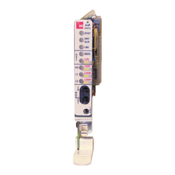
D 1 LOS/BER LED Continuity or SNR alarm LED Loop 1 and Loop 2 Frame sync, CRC, or HDSL BER alarm D 1 transmit/receive onitor jacks Loopback control button Extraction handle S0441-C Figure 1. H4LXC Front Panel LPS-H4TU-C-L5 December 3, 2003... - Page 12 >5 seconds that loopback will be dropped. Extraction handle Pushing up on the extraction handle seats the H4LXC into the backplane card connector. Pulling down on the extraction handle extracts the H4LXC from the backplane card connector. December 3, 2003 LPS-H4TU-C-L5...
-
Page 13: Installation
Open the shipping carton, carefully unpack the module from the protective packing material, and inspect the module. If the equipment has been damaged in transit, immediately report the extent of damage to the transportation company and to ADC Telecommunications, Inc. Contact ADC if there are any for procedures. damages or irregularities. See “Appendix B - Product Support”... - Page 14 “Connecting a Maintenance Terminal to the Craft Port” on page 8), logon the SCU craft interface (see “H4LXC Status Display” on page 13), and set the H4LXC Unit Equip State to EQUIPPED and T1 Provisioning to YES (see “H4LXC Configuration” on page 16). December 3, 2003 LPS-H4TU-C-L5...
-
Page 15: H4Lxr Installation
10 L1 or L2 LOSW/BER is red The HDSL4 loop is not synchronized. Verify that the H4LXR is installed properly; that power is available to the H4LXR; and that all HDSL4 loop connections are completed. LPS-H4TU-C-L5 December 3, 2003... -
Page 16: Scu And H4Lxr Craft Port Interface
Figure 4 for pinouts). Table 4. SCU Craft Port Pinouts Circuit Circuit Name Source CCITT EIA/RS Transmitted Data (TD) Received Data (RD) Frame Ground (FG) – Request to Send (RTS) – (a) Standard references for EIA/RS232 pinouts. December 3, 2003 LPS-H4TU-C-L5... -
Page 17: Logging On To The Craft Maintenance Interface
The following procedure is an example of Logging On to a Soneplex Chassis using SCUv4.1.1. SCU Login Defaults Login: SONEPLEX Password: SONEPLEX1 (use only uppercase characters) Figure 4. Example of Logging On to the Management Interface Using SONEPLEX, SONEPLEX1 LPS-H4TU-C-L5 December 3, 2003... -
Page 18: Navigating The Management Interface
Display current alarms screen. CTRL Display Status screen. CTRL Cancel current operation; cursor moves to the previous menu. CTRL Refresh current screen with last saved values. CTRL Cancel current operation; cursor moves to Main Menu. CTRL December 3, 2003 LPS-H4TU-C-L5... - Page 19 The Craft port includes an EIA-232 DCE connection for a VT100 compatible terminal or PC with VT100 emulation. The Craft port provides a menu-driven interface for viewing the status of and provisioning the H4LXC and associated H4LXR (see Figure Figure 6. SCU Craft Port Interface Menu Tree LPS-H4TU-C-L5 December 3, 2003...
-
Page 20: Provisioning
An “HDSL BER Threshold” setting of 1E-4 or 1E-5 changes to 1E-6 after a (refresh) and cannot CTRL be disabled. • The “T1 BER Threshold” cannot be disabled. • A “Customer Loopback” will appear as both a Customer and Network loopback in the Loopback Status and Trouble Isolation screens. December 3, 2003 LPS-H4TU-C-L5... -
Page 21: H4Lxc Status Display
Figure 8 on H4LX Status H2LX / page 14. Table 7 on page 14 provides a key to the H4LXC status columns in Figure 9 on page 16 Figure 10 on page Figure 7. Display Status Menu LPS-H4TU-C-L5 December 3, 2003... - Page 22 DIS (Disabled) HDSL4 loop is disabled at the locations indicated. LSW (Loss of Sync Word) HDSL4 loop is out of sync at the locations indicated. Tip & Ring Reversal Not applicable Tip and Ring not reversed. Continued December 3, 2003 LPS-H4TU-C-L5...
- Page 23 The current maximum SNR (Margin) value at the locations indicated. TX Power Back-off (dB) D (Default) = 0 to 15 dB Default and Enhanced values are determined by H4LXC module and not reported to SCU for display. E (Enhanced) = 0 to 15 dB LPS-H4TU-C-L5 December 3, 2003...
-
Page 24: H4Lxc Configuration
Starting at the top of Table 8 on page 17 and working your way to the bottom, configure H4LXC fields. Tab from field to field. Figure 9. Unit Configuration Menu Figure 10. H4LX Unit Configuration Screen December 3, 2003 LPS-H4TU-C-L5... - Page 25 H4LXC is capable of triggering an alarm when only, any of the monitored signals degrades below DISABLED for the BER threshold level. SCUv4.1.1) Loop Extender Chassis Toggle Alternate Mark Inversion only: H4LXC T1 Line B8ZS Bipolar Eight-Zero Substitution Code Continued LPS-H4TU-C-L5 December 3, 2003...
- Page 26 Range: 1 dB to 40 dB The highest Pulse Attenuation value allowed +35 dB (SCUv3.6.2), 1 dB to 50 dB on the HDSL4 loop before an alarm is (SCUv4.1.1) triggered. DISABLED Turns off H4LXC PA threshold monitoring. Continued December 3, 2003 LPS-H4TU-C-L5...
- Page 27 “E” settings. The SCU only reports the setting. (c) Set the Loop Power Setting to DISABLED when the remote module is the locally powered H4LXR. The loop-powered H4LXRs require the AUTO, NEG, or POS/NEG Loop Power Setting. LPS-H4TU-C-L5 December 3, 2003...
-
Page 28: Performance Monitoring Reports
Related Publications at the beginning of this manual.) Clearing the Performance Monitoring Reports error counts does not affect current information displayed by the SCU. Figure 11. Performance Monitoring Menu December 3, 2003 LPS-H4TU-C-L5... -
Page 29: Hdsl4 Performance Monitoring Reports Screen
LTPS-UM-8054-01 Provisioning Figure 12. HDSL4 Performance Monitoring Reports Screen Figure 13. HDSL4 Performance Monitoring Reports Screen LPS-H4TU-C-L5 December 3, 2003... - Page 30 DS1 Signal DS1 Signal to network from CPE HDSL4 HDSL4 HDSL4 loop loop loop DS1 Signal DS1 Signal to CPE from Network CEND CRP1 RRP1 CRP2 RRP2 REND S0446-A Figure 14. Location of CEND and REND December 3, 2003 LPS-H4TU-C-L5...
-
Page 31: Inventory Status Display
ISPLAY Use this procedure to display the inventory of the HDSL4 circuit. The Inventory Status screen shows the Unit Identifier, the corresponding ADC part number and catalog number, the module serial number, date code, software version, and CLEI code. From the SCU Main Menu, use the arrow keys or number keys to select 6. -
Page 32: Reset/Led Test Commands
Use the arrow keys to select the module to be reset. Press to execute (the confirmation query shown in Figure 17 appears). Press to reset the module; press to cancel the module reset. Figure 17. Reset/LED Test Screen December 3, 2003 LPS-H4TU-C-L5... -
Page 33: Testing
LOSW/BER LED will be red or blinking green until loop synchronization is complete. When DISP RMT (Display Remote) is initiated from the APU, the STAT, LBK, HDSL4 CONT/SNR, and L1 and L2 LOSW/BER indicators on the H4LXC will illuminate to represent the H4LXR LED conditions. LPS-H4TU-C-L5 December 3, 2003... -
Page 34: H4Lxr End-To-End Test
Press the RLB LBK pushbutton on the H4LXR again for 5 seconds. At the end of 5 seconds, verify that the RLB/LLB LED goes out to indicate that the bi-directional loopback at the CO has dropped. December 3, 2003 LPS-H4TU-C-L5... - Page 35 OFF H4LXR is not ARMed or in loopback Solid yellow H4LXC is looped back toward the network or customer. Flashing yellow once per second System ARMed for loopback. Solid green H4LXR is looped back toward the network or customer. LPS-H4TU-C-L5 December 3, 2003...
-
Page 36: Trouble Isolation Display
Group and Slot fields. The SPACEBAR trouble isolation screen displays a circuit status diagram and three information fields (Equipment, DS-1 and HDSL4). Table 11 on page 29 defines the types of status that can be reported. December 3, 2003 LPS-H4TU-C-L5... - Page 37 No data available A Disabled alarm is being reported for the specified loop A PM alarm is indicated for the specified loop Pulse attenuation/signal-to-noise ratio PA/SNR Indicates the location of the DS1 status reading Flashing X LPS-H4TU-C-L5 December 3, 2003...
-
Page 38: Alarms
1. Alarms if using the arrow keys.) The Alarms Menu ENTER Figure 19). appears (see Select 1. Display Active Alarms to display the Active Alarms screen 1. Display Active (see Figure 20). Alarms Figure 19. Alarms Menu December 3, 2003 LPS-H4TU-C-L5... -
Page 39: Alarm Summary
HSK = Housekeeping REM = Remote Most severe PWR = Power alarms ACO = ACO Active 5 = Critical 4 = Major 3 = Minor 2 = Event 1 = Not Reported Figure 21. Alarm Summary Screen LPS-H4TU-C-L5 December 3, 2003... -
Page 40: Alarm History
Figure 23. Network and Customer Loopbacks Dual Loopbacks Dual (bidirectional) loopbacks can be initiated from the SCU Craft Port Interface or by pressing the LBK pushbutton on the H4LXC or the LLB or RLB pushbuttons on the H4LXR front panel. December 3, 2003 LPS-H4TU-C-L5... -
Page 41: Programmable Loopbacks
Soneplex Broadband or Loop Extender systems, the network loopbacks can be activated by the Craft Port Interface Menu or TL1 command. The standard inband (SF format) and out-of-band (ESF format) loopback codes activate or deactivate the customer loopback. LPS-H4TU-C-L5 December 3, 2003... -
Page 42: Running Line Card Loopbacks
IN SERVICE, T1 provision is YES, T1 service state is IN SERVICE, and T1 framing format is ESF. If disabled, the ESF loopback codes will only be active out of band. H4LXR NID/Smartjack Lpbk Select either ENABLED or DISABLED. ENABLED activates response to NID loopback codes. Continued December 3, 2003 LPS-H4TU-C-L5... -
Page 43: Loopback Status And Commands
Select ACT NET, ACT CUST, SEND LPBK, or DEACTIVATE, then press . A blank field ENTER indicates no selection. (See Table 13 on page 36 for descriptions of loopback selection field options.) The following message appears: LPS-H4TU-C-L5 December 3, 2003... - Page 44 “LPBK RQ>” that appears on the loopback screen. SEND LPBK can only be activated when the DS1 Loopback Mode parameter on the Broadband DS3 MUX Configuration screen is configured as C-Bit parity. December 3, 2003 LPS-H4TU-C-L5...
- Page 45 -40°F to 158°F (-40°C to 70°C) Humidity 5% to 95%, operating and storage Non-condensing Physical Dimensions (H x W x D) 4.6 inches x 0.7 inches x 9.5 inches (11.7 cm x 1.7 cm x 24.1 cm) LPS-H4TU-C-L5 December 3, 2003...
- Page 46 DS1 In Tip HDSL4 Loop1 Tip HDSL4 Loop1 Tip D 1 In Ring HDSL4 Loop2 Ring HDSL4 Loop2 Ring DS1 Out Tip DS1 Out Ring -48V Return B -48V Battery B S0445-A Figure 26. LPS-H4TU-C Card Connector December 3, 2003 LPS-H4TU-C-L5...
- Page 47 UPPORT ADC Customer Service Group provides expert pre-sales and post-sales support and training for all its products. Technical support is available 24 hours a day, 7 days a week by contacting the ADC Technical Assistance Center. Sales Assistance • Quotation Proposals 800.366.3891...
- Page 48 Superframe SNR: Signal-to-noise ratio SNR-L: Signal-to-Noise Ratio-Low H2LX: HDSL2 CO Line Unit H4LX: HDSL4 CO Line Unit H4LXC: HDSL4 CO Line Unit UAS: Unavailable Seconds H4LXR: HDSL4 Remote Line Unit HLX: HDSL CO Line Unit In-Service December 3, 2003 LPS-H4TU-C-L5...
- Page 49 ODIFICATIONS Any changes or modifications made to this device that are not expressly approved by ADC Telecommunications, Inc. voids the user's warranty. All wiring external to the products should follow the provisions of the current edition of the National Electrical Code.
- Page 50 World Headquarters ADC Telecommunications, Inc. PO Box 1101 Minneapolis, MN 55440-1101 USA For Technical Assistance Tel: 800.366.3891 ISO 9001/TL 9000 DNV Certification, Inc. REGISTERED FIRM :LTPS-UM-8054-01 OCUMENT ´,eN¶8y¨ 1269468...
Need help?
Do you have a question about the LPS-H4TU-C-L5 and is the answer not in the manual?
Questions and answers