Advertisement
Quick Links
Advertisement

Related Manuals for ADC LPS-H4TU-C-L5


Summary of Contents for ADC LPS-H4TU-C-L5
- Page 1 UICK NSTALLATION LPS-H4TU-C-L5 CO L...
-
Page 2: Specifications
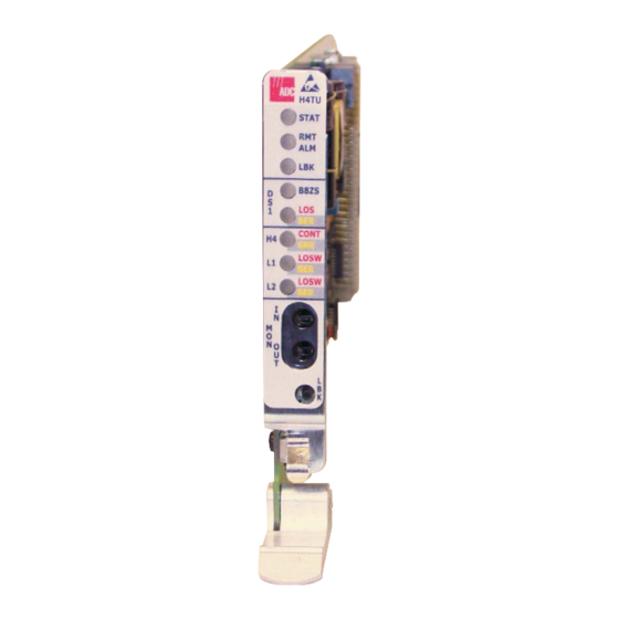
LPS-H4TU-C-L5 The LPS-H4TU-C-L5 (LPS-H4TU-C) line unit is the Central Office (CO) side of a T1 transmission system. The LPS-H4TU-C, when used with an H4TU-R-402-5A remote unit, transmits a 1.544 Mbps payload a maximum distance of 12 kft. (26 AWG) over two unconditioned copper pairs. -
Page 3: Installation
NSTALLATION LPS-H4TU-C ESD strap input S0276-A Align the LPS-H4TU-C with the chassis slot guides (Loop Extender chassis, Broadband chassis, or LoopStar) and slide the unit in until it touches the backplane connector. Raise the extraction lever at the bottom of the front panel to press the LPS-H4TU-C into the backplane connector. - Page 4 Status LED Row A Row B Row C H4TU Remote Alarm LED -48V Return A -48V Battery A Loopback LED DS1 line code LED D 1 LOS/BER LED DS1 In Tip HDSL4 Loop 2 Tip HDSL4 Loop 1 Tip Continuity or SNR alarm LED D 1 In Ring HDSL4 Loop 2 Ring HDSL4 Loop 1 Ring...
- Page 5 ERIFICATION Once the LPS-H4TU-C-L5 is installed, verify that it is operating properly by monitoring the Status LEDs on the front panel. Table 1. Status LED Descriptions Description STAT Displays results of self-test diagnostics and initiation status. Red Internal fault detected during diagnostics.
- Page 6 For more detailed information about the maintenance terminal screens, refer to the Soneplex Shelf Controller Unit (SCU) V4.1 User manual (LTPS-UM-8031-xx) and the line LPS-H4TU-C-L5 CO Line Unit User Manual (LTPS-UM-8054-xx). Copies of this publication or those listed above can be downloaded from the ADC website at www.adc.com.
- Page 7 Customer Service for details. Modifications Any changes or modifications made to this device that are not expressly approved by ADC DSL Systems, Inc. voids the user's warranty. All wiring external to the products should follow the provisions of the current edition of the National Electrical Code.
Need help?
Do you have a question about the LPS-H4TU-C-L5 and is the answer not in the manual?
Questions and answers