Table of Contents
Advertisement
Quick Links
APsystems Microinverter User Manual
ALTENERGY POWER SYSTEM Inc.
latam.APsystems.com
APsystems
APsystems Guadalajara:
AV. Lazaro Cardenas 2850-5º Piso, Colonia Jardines del Bosque
P. 44520, Guadalajara, Jalisco
TEL: 52 (33) -3188-4604 EMAIL: info.latam@APsystems.com
© All Rights Reserved
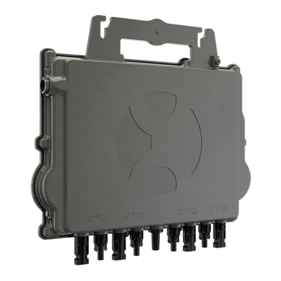
APsystems QT2D 3-Phase Microinverter
(For Brazil)
Please scan this QR code to
have access to our APPs and
Products information
Advertisement
Table of Contents

Related Manuals for APsystems QT2D


Summary of Contents for APsystems QT2D
- Page 1 APsystems APsystems Guadalajara: Please scan this QR code to AV. Lazaro Cardenas 2850-5º Piso, Colonia Jardines del Bosque have access to our APPs and Products information P. 44520, Guadalajara, Jalisco TEL: 52 (33) -3188-4604 EMAIL: info.latam@APsystems.com © All Rights Reserved...
-
Page 2: Table Of Contents
4.3.3 Step 3 - Attach the APsystems Microinverters to the Racking........9 4.3.4 Step 4 - Ground the system....................10 4.3.5 Step 5 - Connect the APsystems microinverter to AC bus cable......11 4.3.6 Step 6 - Install a Bus Cable End Cap at the end of AC bus cable......12 4.3.7 Step 7 - Connect APsystems Microinverters to the PV Modules...... -
Page 3: Important Safety Instructions
Do NOT disconnect the PV module from the APsystems Microinverter without first disconnecting the AC power. Be aware that the body of the APsystems Microinverter is the heat sink and can reach a temperature of 80°C. To reduce risk of burns, do not touch the body of the Microinverter. -
Page 4: Radio Interference Statement
1. Important Safety Instructions 1.2 Radio Interference Statement EMC Compliance : The APsystems Microinverter can radiate radio frequency energy. If not installed and used in accordance with the instructions, it may cause harmful interference to radio communication. APsystems Microinverter complies with EMC regulations, which are designed to provide reasonable protection against harmful interference in a residential installation. -
Page 5: Symbols Replace Words On The Equipment, On A Display, Or In Manuals
EMC and is authorized to energize, ground, and tag equipment, systems, and personnel circuits in accordance with established safety procedures. The inverter and photovoltaic system may only be commissioned and operated by qualified personnel. APsystems Microinverter QT2D User Manual... -
Page 6: Apsystems Microinverter System Introduction
2. APsystems Microinverter System Introduction The APsystems Microinverter is used in utility-interactive grid-tied applications, comprised of three key elements: APsystems Microinverter APsystems Energy Communication Unit (ECU) APsystems Energy Monitor and Analysis (EMA) web-based monitoring and analysis system... - Page 7 This extreme high DC voltage brings a risk of electrical shocks or electrical arcs which could cause fire in a worst case scenario. When using an APsystems microinverter, each 1 or 2 PV modules are connected to DC input. Voltage at the back of each PV module never exceeds PV...
-
Page 8: Apsystems Microinverter Qt2D Introduction
The new QT2D is interactve with power grids through a feature referred to as RPC (Reactve Power Control) to beter manage photovoltaic power spikes in the grid. In additon, it provides 97% peak efciency with 20% less components compared to the last generaton product. -
Page 9: Apsystems Microinverter System Installation
4. APsystems Microinverter System Installation A PV system using APsystems Microinverters is simple to install. Each Microinverter easily mounts on the PV racking, directly beneath the PV module(s). Low voltage DC wires connect from the PV module directly to the Microinverter, eliminating the risk of high DC voltage. -
Page 10: Installation Procedures
It is strictly prohibited to hand carry the microinverter by its AC cable. 4.3.3 Step 3 - Attach the APsystems Microinverters to the Racking a. Mark the location of the microinverter on the rack, with respect to the PV module junction box or any other obstructions. -
Page 11: Step 4 - Ground The System
The racking must be properly grounded as per local electrical code. 4.3.4 Step 4 - Ground the system There're 2 ways to ground the QT2D series microinverters. 1. By grounding washer attached. After the microinverters and racking are reliably installed, the microinverter's grounding washer can connect to the racking to ensure proper earthing. -
Page 12: Step 5 - Connect The Apsystems Microinverter To Ac Bus Cable
4. APsystems Microinverter System Installation 4.3.5 Step 5 - Connect the APsystems microinverter to AC bus cable Insert the microinverter AC connector into the trunk cable connector. Make sure to hear the “click” as a proof of robust connection Click Figure 4 Best Practice: Use the Bus Cable Unlock Tool of AC Bus to disconnect the connectors. -
Page 13: Step 6 - Install A Bus Cable End Cap At The End Of Ac Bus Cable
Body Seal Figure 8 4.3.7 Step 7 - Connect APsystems Microinverters to the PV Modules ..Figure 9 Each channel connects 2 PV modules in series (For PV modules with Voc<60V).The input channel will not work if connects to a single module(Voc<60V). That means the quantity of PV modules in the sysem is even number. -
Page 14: Step 8 - Complete The Apsystems Installation Map
4.3.8 Step 8 - Complete the APsystems installation map a. Each APsystems Microinverter has 2 removable serial number labels. b. Complete installation map by sticking ID label of each microinverter at the right location. -
Page 15: Apsystems Microinverter System Operating Instructions
Alternatively, LED sequences could be an indicator of microinverters status (see section 6.1) Once the ECU has been commissioned properly, the APsystems Microinverters will start to send performance data to the ECU. The time required for all of the Microinverters in the system to report to the ECU will vary depending on the number of Microinverters in the system. -
Page 16: Troubleshooting
APsystems Technical Support. 6.2 ECU_APP APsystems ECU_APP (available in the EMA Manager APP) is the recommended tool to do on-site troubleshooting. When connecting the ECU_APP to the ECU hotspot (please check ECU User Manual for more detailed information), installer can check every microinverter status (production, communication) but also ZigBee signal strength, grid profile and other insightful data helping the troubleshooting. -
Page 17: Apsystems Technical Support
6. Troubleshooting 6.5 APsystems Technical Support APsystems local Technical Support team is available to support professional installers to get familiar with our products and to troubleshoot installations when needed. Do not attempt to repair APsystems Microinverters. Please contact your local APsystems Technical Support. -
Page 18: Replace A Microinverter
7. Replace a microinverter Follow the procedure to replace a failed APsystems Microinverter A. Disconnect the APsystems Microinverter from the PV Module, in the order shown below: 1. Disconnect the AC by turning off the branch circuit breaker. 2. Disconnect the inverter AC connector from the AC Bus. -
Page 19: Technical Data
8. Technical Data ①. Be sure to verify that the voltage and current specifications of your PV module are compatible with the range allowed on APsystems Microinverter. Please check the microinverter datasheet. ②. DC operating voltage range of the PV module must be within allowable input voltage range of the APsystems Microinverter. -
Page 20: Qt2D 3-Phase Microinverter Datasheet
④ Recommend no more than 80 inverters register to one ECU for stable communication. ⑤ To be eligible for the warranty, APsystems microinverters need to be monitored via the EMA portal. Please refer to our warranty T&Cs available on latam.APsystems.com ©... -
Page 21: Qt2D - Wiring Diagram
9. QT2D - Wiring Diagram 9.1 Sample Wiring Diagram SOLAR PANEL AC JUNCTION BOX ENERGY COMMUNICATION UNIT DISTRIBUTION PANEL Figure 12 Each channel connects 2 PV modules in series (For PV modules with Voc<60V).The input channel will not work if connects to a single module(Voc<60V). That means the quantity of PV modules in the sysem is even number. -
Page 22: Apsystems Microinverter Installation Map
10. APsystems Microinverter Installation Map The APsystems Installation Map is a diagram of the physical location of each microinverter in your PV installation. Each APsystems microinverter has two serial number labels. Peel the one label and affix it to the respective location on the APsystems installation map.
Need help?
Do you have a question about the QT2D and is the answer not in the manual?
Questions and answers