Table of Contents
Advertisement
Quick Links
APsystems Microinverter Installation manual
ALTENERGY POWER SYSTEM Inc.
emea.APsystems.com
APsystems
Karspeldreef 8, 1101 CJ, Amsterdam, The Netherlands
EMAIL: info.emea@APsystems.com
APsystems
22 Avenue Lionel Terray 69330 Jonage France
EMAIL:info.emea@APsystems.com
© All Rights Reserved
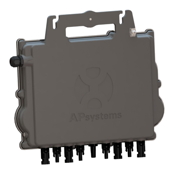
APsystems QT2 Microinverter
Please scan this QR code to have
access to our APPs and Products
information
(For EMEA)
Advertisement
Table of Contents

Related Manuals for APsystems QT2-EU


Summary of Contents for APsystems QT2-EU
- Page 1 APsystems Microinverter Installation manual APsystems QT2 Microinverter (For EMEA) ALTENERGY POWER SYSTEM Inc. emea.APsystems.com APsystems Karspeldreef 8, 1101 CJ, Amsterdam, The Netherlands EMAIL: info.emea@APsystems.com Please scan this QR code to have access to our APPs and Products APsystems information 22 Avenue Lionel Terray 69330 Jonage France EMAIL:info.emea@APsystems.com...
-
Page 2: Table Of Contents
4.3.4 Step 4 - Ground the system .......................10 4.3.5 Step 5 - Connect the APsystems microinverter to AC bus cable ............10 4.3.6 Step 6 - Install a Bus Cable End Cap at the end of AC bus cable ............11 4.3.7 Step 7 - Connect APsystems Microinverters to the PV Modules ............12... -
Page 3: Important Safety Instructions
Do NOT disconnect the PV module from the APsystems Microinverter without first disconnecting the AC power. Be aware that the body of the APsystems Microinverter is the heat sink and can reach a temperature of 80°C. To reduce risk of burns, do not touch the body of the Microinverter. -
Page 4: Radio Interference Statement
1. Important Safety Instructions 1.2 Radio Interference Statement EMC Compliance:The APsystems Microinverter can radiate radio frequency energy. If not installed and used in accordance with the instructions, it may cause harmful interference to radio communication. APsystems Microinverter complies with EMC regulations, which are designed to provide reasonable protection against harmful interference in a residential installation. -
Page 5: Symbols In Lieu Of Words
EMC and is authorized to energize, ground, and tag equipment, systems, and circuits in accordance with established safety procedures. The inverter and photovoltaic system may only be commissioned and operated by qualified personnel. APsystems Microinverter QT2 Installation manual... -
Page 6: Apsystems Microinverter System Introduction
2. APsystems Microinverter System Introduction The APsystems Microinverter is used in utility-interactive grid-tied applications, comprised of three key elements: APsystems Microinverter APsystems Energy Communication Unit (ECU) APsystems Energy Monitor and Analysis (EMA) web-based monitoring and analysis system... - Page 7 Simple to install APsystems Microinvertes are compatible with most of 60 and 72 cell PV modules or 120 and 144 half-cut cells PV modules. (In order to confirm compatibility of PV module with APsystems microinverter, feel free to check our online module compatibility tool or contact your local APsystems Technical Support).
-
Page 8: Apsystems Microinverter Qt2 Introduction
3. APsystems Microinverter QT2 Introduction APsystems 2 generation of native 3-phase quad microinverters are reaching unprecedented power outputs of 2000VA to adapt to today’s larger power PV modules. With balancing 3-phase output, 4 DC inputs, encrypted ZigBee signals, the QT2 benefits from an entirely new architecture. -
Page 9: Apsystems Microinverter System Installation
4. APsystems Microinverter System Installation A PV system using APsystems Microinverters is simple to install. Each Microinverter easily mounts on the PV racking, directly beneath the PV module(s). Low voltage DC wires connect from the PV module directly to the Microinverter, eliminating the risk of high DC voltage. -
Page 10: Installation Procedures
4.3.3 Step 3 - Attach the APsystems Microinverters to the Racking a. Mark the location of the microinverter on the rack, with respect to the PV module junction box or any other obstructions. -
Page 11: Step 4 - Ground The System
Fix the grounding copper wire by the grounding lug. grounding lug Figure 4 4.3.5 Step 5 - Connect the APsystems microinverter to AC bus cable Insert the microinverter AC connector into the trunk cable connector. Make sure to hear the “click” as a proof of robust connection... -
Page 12: Step 6 - Install A Bus Cable End Cap At The End Of Ac Bus Cable
4. APsystems Microinverter System Installation AC connector interface as from left to right. PE N L3 L2 L1 Figure 6 Cover any unused connectors with Bus Cable T-CONN Cap to protect the unused connectors. Figure 7 4.3.6 Step 6 - Install a Bus Cable End Cap at the end of AC bus cable C. -
Page 13: Step 7 - Connect Apsystems Microinverters To The Pv Modules
4. APsystems Microinverter System Installation 4.3.7 Step 7 - Connect APsystems Microinverters to the PV Modules Figure 9 Remove the DC connector caps before PV modules connection . The neutral wire is not mandatory to be connected to grid. -
Page 14: Step 8 - Connect Apsystems Microinverters To Grid
When AC extension cable is needed, users could connect the AC bus cable and AC extension cable in a junction box or use a pair of male/female AC connectors that APsystems provides as optional accessory. APsystems Microinverter QT2 Installation manual... -
Page 15: Step 10 - Complete The Apsystems Installation Map
4. APsystems Microinverter System Installation 4.3.10 Step 10 - Complete the APsystems installation map a. Each APsystems Microinverter has 2 removable serial number labels. b. Complete installation map by sticking ID label of each microinverter at the right location. c. The second serial number label, could be stuck on the solar module frame, which could help later to... -
Page 16: Apsystems Microinverter System Operating Instructions
Alternatively, LED sequences could be an indicator of microinverters status (see section 6.1) Once the ECU has been commissioned properly, the APsystems Microinverters will start to send performance data to the ECU. The time required for all of the Microinverters in the system to report to the ECU will vary depending on the number of Microinverters in the system. -
Page 17: Troubleshooting
Please contact your local APsystems Technical Support. 6.2 ECU_APP APsystems ECU_APP (available in the EMA Manager APP) is the recommended tool to do on-site troubleshooting. When connecting the ECU_APP to the ECU hotspot (please check ECU User Manual for more detailed information), installer can check every microinverter status (production, communication) but also ZigBee signal strength, grid profile and other insightful data helping the troubleshooting. -
Page 18: Apsystems Technical Support
6. Troubleshooting 6.5 APsystems Technical Support APsystems local Technical Support team is available to support professional installers to get familiar with our products and to troubleshoot installations when needed. Do not attempt to repair APsystems Microinverters. Please contact your local APsystems Technical Support. -
Page 19: Replace A Microinverter
7. Replace a microinverter Follow the procedure to replace a failed APsystems Microinverter A. Disconnect the APsystems Microinverter from the PV Module, in the order shown below: 1. Disconnect the AC by turning off the branch circuit breaker. 2. Disconnect the inverter AC connector from the AC Bus. -
Page 20: Technical Data
①. Be sure to verify that the voltage and current specifications of your PV module are compatible with the range allowed on APsystems Microinverter. Please check the microinverter datasheet. ②. DC operating voltage range of the PV module must be within allowable input voltage range of the APsystems Microinverter. -
Page 21: Qt2 3-Phase Microinverter Datasheet
(4) Recommend no more than 80 inverters register to one ECU for stable communication. (5) To be eligible for the warranty, APsystems microinverters need to be monitored via the EMA portal. Please refer to our warranty T&Cs available on emea.apsystem.com. -
Page 22: Qt2 - Wiring Diagram
9. QT2 - Wiring Diagram 9.1 QT2 Connected To Detla Type 3-Phase Grid Neutral wire could be floating for delta grid. Figure 14 APsystems Microinverter QT2 Installation manual... -
Page 23: Qt2 Connected To Wye 3-Phase Grid
9. QT2 - Wiring Diagram 9.2 QT2 Connected To Wye 3-Phase Grid Figure 15 APsystems Microinverter QT2 Installation manual... -
Page 24: Qt2 Accessory
10.QT2 Accessory 10.1 Dimensions Figure 16 APsystems Microinverter QT2 Installation manual... -
Page 25: Wiring Diagram
10.QT2 Accessory 10.2 Wiring Diagram Figure 17 APsystems Microinverter QT2 Installation manual... -
Page 26: Apsystems Microinverter Installation Map
11.APsystems Microinverter Installation Map The APsystems Installation Map is a diagram of the physical location of each microinverter in your PV installation. Each APsystems microinverter has two serial number labels. Peel the one label and affix it to the respective location on the APsystems installation map.
Need help?
Do you have a question about the QT2-EU and is the answer not in the manual?
Questions and answers