APsystems QT2 Quick Installation Manual
Microinverter
Hide thumbs
Also See for QT2:
- Manual (37 pages) ,
- Installation manual (24 pages) ,
- Quick installation manual (4 pages)
Table of Contents
Advertisement
Quick Links
Please scan the QR code to get
mobile app and more support
to help the installation.
Step 1. Verify that grid voltage matches microinverter rating
Step 2. AC Bus Cable distribution
a. One end of the AC bus cable is used to access the junction box into the power grid.
b. Wire the conductors of the AC bus: L1- BROWN; L2 - BLACK; L3 - GRAY; N - BLUE; PE – YELLOW GREEN.
NOTE: Wiring color code can be different according to the local regulation. Check all the wires of the installation before
connecting to the AC bus to be sure they match. Wrong cabling can damage irreparably the microinverters: such damage
is not covered by the warranty.
Step 3. Attach the APsystems Microinverters to the Racking
NOTE: Install the microinverters (including DC and AC connectors) under the PV modules to avoid direct exposure to rain,
UV or other harmful weather events. Allow a minimum of 1.5cm (3/4'') below and above the casing of the microinverter
to allow proper air flow. The racking must be properly grounded as per local electrical code.
ATTENTION: Do NOT carry the microinverter by the AC cable. This may cause the AC cable to partially or fully disconnect
from the unit, resulting in no or poor operation.
a. Mark the location of the microinverter on the rack, with
respect to the PV module junction box or any other
obstructions.
b. Mount one microinverter at each of these locations using
hardware recommended by your module racking vendor.
Step 4. Ground the system
There're 2 ways to ground the QT2 series microinverters.
1. By grounding washer attached.
After the microinverters and racking are reliably installed,
the microinverter's grounding washer can connect to the
racking to ensure proper earthing.
2. By grounding copper wire.
Fix the grounding copper wire by the grounding lug.
Step 5. Connect the APsystems microinverter to AC bus cable
Insert the microinverter AC connector into the trunk cable
connector. Make sure to hear the "click" as a proof of robust
connection.
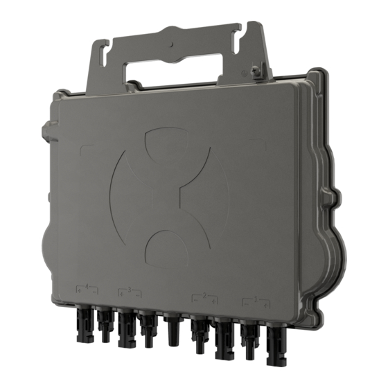
①NOTE: AC connector interface as from left to right.
②NOTE: Cover any unused connectors with Bus Cable T-CONN Cap
to protect the unused connectors.
Step 6. Install a Bus Cable End Cap at the end of AC bus cable
A. Wire stripping
QT2 Microinverter Quick Installation Guide
B. Set the parts on the cable
Nut/Claw Seal/body/Body
M8 (Not supplied by
Apsystems)
PE N L3 L2 L1
C. Insert five wires into
the core wires hole of the
body
1
2022/12/22
grounding washer
Warning injure hand
grounding
lug
Click
②
①
D. Insert seal and Clamp
Finger into the body, then
tighten the nut, torque
2.5±0.5N.m
Rev2.1
Quick Installation Guide
Advertisement
Table of Contents

Subscribe to Our Youtube Channel
Related Manuals for APsystems QT2


Summary of Contents for APsystems QT2
- Page 1 Step 4. Ground the system There're 2 ways to ground the QT2 series microinverters. 1. By grounding washer attached. After the microinverters and racking are reliably installed, the microinverter's grounding washer can connect to the racking to ensure proper earthing.
- Page 2 Step 7. Place the PV modules and connect each QT2 to the PV modules NOTE: When plugging in the DC cables, the microinverter should immediately blink green ten times. This will happen as soon as the DC cables are plugged in and will show that the microinverter is functioning correctly.
Need help?
Do you have a question about the QT2 and is the answer not in the manual?
Questions and answers