Table of Contents
Advertisement
Quick Links
Advertisement
Table of Contents

Subscribe to Our Youtube Channel
Related Manuals for Darfon H5001


Summary of Contents for Darfon H5001
- Page 1 INSTALLATION MANUAL H5001 HYBRID INVERTER...
-
Page 2: Table Of Contents
I N S T A L L A T I O N M A N U A L H 5 0 0 1 H Y B R I D I N V E R T E R TABLE OF CONTENTS IMPORTANT SAFETY WARNINGS ........................ -
Page 3: Important Safety Warnings
CAUTION. Damages or malfunctions due to misuse, abuse, negligence, power surges, fire, natural disasters, pests, direct exposure to sea water, force majeure, or other unforeseeable circumstances outside the range of influence of Darfon are not covered under warranty. -
Page 4: Product Overview
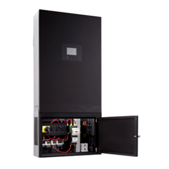
I N S T A L L A T I O N M A N U A L H 5 0 0 1 H Y B R I D I N V E R T E R PRODUCT OVERVIEW Distribution Box Power Switch Cooling Fans... -
Page 5: Dead-Front Cover
I N S T A L L A T I O N M A N U A L H 5 0 0 1 H Y B R I D I N V E R T E R Dead-Front Cover Notes Remove the screws from the dead- Pull off the dead-front cover. -
Page 6: Operational Modes
I N S T A L L A T I O N M A N U A L H 5 0 0 1 H Y B R I D I N V E R T E R OPERATIONAL MODES Mode Definitions There are eight modes of operation: Back-up, Residential, Back-up w/o Feed-in, Residential w/o Feed-in, TOU w/o Batt. -
Page 7: System Design
Soft start devices should be installed to limit the power surges of any equipment with large inrush currents. Parallel Operation Up to 3 H5001 can be connected in parallel. Each H5001 has its own charging 1x H5001 2x H5001 3x H5001 capability and can be controlled to work together, so you can incrementally add Max. -
Page 8: Connections
I N S T A L L A T I O N M A N U A L H 5 0 0 1 H Y B R I D I N V E R T E R CONNECTIONS Notes Wire/Cable Requirements ... -
Page 9: Battery Charging Requirements
PORT FUNCTION RJ45 For External Display. The inverter can only connect to external displays provided by Darfon. RJ12 (x2) For Parallel (Stacking) Function. Only inverters of the same model can be installed in parallel. RS485 S For Data Logger. -
Page 10: Access Panel
I N S T A L L A T I O N M A N U A L H 5 0 0 1 H Y B R I D I N V E R T E R Access Panel The access panel is used to manually update the inverter’s firmware. The inverter’s firmware can typically be updated via the internet and data logger. -
Page 11: Turning The System On/Off
I N S T A L L A T I O N M A N U A L H 5 0 0 1 H Y B R I D I N V E R T E R TURNING THE SYSTEM ON/OFF Turning On the System Turn on the battery breaker if Turn on the battery. -
Page 12: Operation And Display Panel
I N S T A L L A T I O N M A N U A L H 5 0 0 1 H Y B R I D I N V E R T E R OPERATION AND DISPLAY PANEL Display Overview Enters System Settings page or confirms selection. -
Page 13: Changing The Mode Of Operation
Battery Type. to select it. BATTERY TYPE None Lead-Acid Darfon LNMC Panasonic Darfon LFP You will see a message stating the When you see “Setting OK!!” Manually restart the inverter using the settings are being updated. -
Page 14: Appendix A: Maintenance
NOTES: The H5001 has L1 and L2 connections for two AC input sources, although it can only accept one source at a time. The H5001 has separate neutral connections for grid input, generator input and output. These are electrically common. The distribution box is both an input conduit box and an AC load center. -
Page 15: Error And Warning Definition
I N S T A L L A T I O N M A N U A L H 5 0 0 1 H Y B R I D I N V E R T E R Error and Warning Definition On the Power Flows Page, the icon will flash when there is an error. - Page 16 I N S T A L L A T I O N M A N U A L H 5 0 0 1 H Y B R I D I N V E R T E R CODE FAULT EVENT ALARM ICON SOLUTION...
-
Page 17: Appendix B: Specifications
I N S T A L L A T I O N M A N U A L H 5 0 0 1 H Y B R I D I N V E R T E R APPENDIX B: SPECIFICATIONS SOLAR DC INPUT Nominal Power 6500W... -
Page 18: Appendix C: Current Sensor [Sold Separately]
I N S T A L L A T I O N M A N U A L H 5 0 0 1 H Y B R I D I N V E R T E R APPENDIX C: CURRENT SENSOR [SOLD SEPARATELY] Notes CT Sensor Rating ... -
Page 19: Appendix D: Emergency Shutdown Button [Sold Separately]
I N S T A L L A T I O N M A N U A L H 5 0 0 1 H Y B R I D I N V E R T E R APPENDIX D: EMERGENCY SHUTDOWN BUTTON [SOLD SEPARATELY] Wiring the Emergency Shutdown Button to the Inverter Turn off the system. -
Page 20: Testing The Emergency Button
I N S T A L L A T I O N M A N U A L H 5 0 0 1 H Y B R I D I N V E R T E R Testing the Emergency Button Turn on the system and wait for it to bootup. - Page 21 Tel: +886 3 2508800 Tel: +1.650.316.6300 ©2022 Darfon Electronics Corp. All rights reserved. All specifications are subject to change without prior notice. Darfon and the Darfon logo are trademarks of Darfon Electronics Corp. All other trademarks are the property of the respective owners.
Need help?
Do you have a question about the H5001 and is the answer not in the manual?
Questions and answers