
Related Manuals for Darfon H5001


Summary of Contents for Darfon H5001
- Page 1 I N V E R T E R INSTALLATION MANUAL H5001 HYBRID INVERTER R e v . 2 © 2 0 1 8 D a r f o n E l e c t r o n i c s C o r p .
-
Page 2: Table Of Contents
I N S T A L L A T I O N M A N U A L H 5 0 0 1 H Y B R I D I N V E R T E R TABLE OF CONTENTS IMPORTANT SAFETY WARNINGS ................... -
Page 3: Important Safety Warnings
Tel: +1.650.316.6300 © 2018 Darfon Electronics Corp. All rights reserved. All specifications are subject to change without prior notice. Darfon and the Darfon logo are trademarks of Darfon Electronics Corp. All other trademarks are the property of the respective owners. -
Page 4: Product Overview
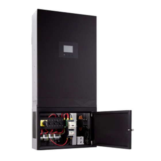
PRODUCT OVERVIEW BASIC HYBRID PV STORAGE SYSTEM OVERVIEW The H5001 hybrid inverter provides power to the essential load by utilizing power from PV panels, the utility and batteries. When the PV panels (two string input) generates enough power, the inverter supports the essential load, feeds back to the grid and charges the batteries, all at the same time. -
Page 5: Mounting The Inverter
Before installation, make sure nothing inside the package is damaged. You should have received the following items in the package: H5001 hybrid inverter, backplate, brackets, screws and this installation manual. The following considerations must be taken into account when selecting where to install. -
Page 6: Removing And Installing The Dead-Front Cover
I N S T A L L A T I O N M A N U A L H 5 0 0 1 H Y B R I D I N V E R T E R REMOVING AND INSTALLING THE DEAD-FRONT COVER Before making any connections (PV, Grid, Battery or Load), you will need to first remove the dead-front cover from the distribution box. -
Page 7: Pv Module (Dc) Connection
PV modules will cause leakage current to the inverter. CAUTION. To reduce the risk of damage due to surge, Darfon recommends surge protection between the modules and the inverter. CAUTION. To reduce the risk of injury, use the proper cable size for PV module connection. -
Page 8: Grid (Utility) Connection
I N S T A L L A T I O N M A N U A L H 5 0 0 1 H Y B R I D I N V E R T E R GRID (UTILITY) CONNECTION There is an AC (Grid) circuit breaker in the distribution box. -
Page 9: Battery Connection And Charging Requirements
I N S T A L L A T I O N M A N U A L H 5 0 0 1 H Y B R I D I N V E R T E R BATTERY CONNECTION AND CHARGING REQUIREMENTS There is a DC (Battery) circuit breaker in the distribution box. -
Page 10: Battery Charging Requirements
The default charging parameters are shown below. Use this as a reference to make sure the battery selected is compatible with H5001 inverter. It is recommended that you use a deep cycle battery when the mode of operation is not set as one of the two back-up modes. -
Page 11: Load (Ac Output) Connection
I N S T A L L A T I O N M A N U A L H 5 0 0 1 H Y B R I D I N V E R T E R LOAD (AC OUTPUT) CONNECTION There are two AC circuit breakers inside the distribution box for the load connection;... -
Page 12: Operation And Display Panel
I N S T A L L A T I O N M A N U A L H 5 0 0 1 H Y B R I D I N V E R T E R OPERATION AND DISPLAY PANEL Display Panel Overview The display panel consists of four function keys and an LCD screen. -
Page 13: Lcd Screen - Icons And Pages
I N S T A L L A T I O N M A N U A L H 5 0 0 1 H Y B R I D I N V E R T E R LCD Screen – Icons and Pages The LCD screen will display three different pages: “Power Flows”, “Power Information”... - Page 14 I N S T A L L A T I O N M A N U A L H 5 0 0 1 H Y B R I D I N V E R T E R Mode Rule Definition There are eight modes of operation: Back-up, Residential, Back-up w/o Feed-in, Residential w/o Feed-in, TOU w/o Batt.
-
Page 15: System Settings
Please re-turn on the main switch and re-setting the leftside of the inverter. the mode again. If still get a setting fail message, please contact your Darfon representative. B. Setting System Time Step 1. In the System Setting Page, Step 2. Enter the date in format DD/MM/YYYY, and the time in format hh:mm:ss. - Page 16 Please re-turn on the main switch and re-setting the mode again. If the leftside of the inverter. still get a setting fail message, please contact your Darfon representative. C. Setting Battery Type. ← → ←...
-
Page 17: Error And Warning Definition
I N S T A L L A T I O N M A N U A L H 5 0 0 1 H Y B R I D I N V E R T E R Error and Warning Definition On the Power Flows Page, the icon will flash when there is an error. - Page 18 I N S T A L L A T I O N M A N U A L H 5 0 0 1 H Y B R I D I N V E R T E R CODE FAULT EVENT ALARM ICON SOLUTION...
-
Page 19: Generator [Generator Kit Sold Separately]
I N S T A L L A T I O N M A N U A L H 5 0 0 1 H Y B R I D I N V E R T E R GENERATOR [GENERATOR KIT SOLD SEPARATELY] The inverter can only work with “split-phase”... -
Page 20: Configuring The Hardware
I N S T A L L A T I O N M A N U A L H 5 0 0 1 H Y B R I D I N V E R T E R CONFIGURING THE HARDWARE Connecting to the Hardware Step 1. -
Page 21: Using The Application Software
Step 4. Turn on the inverter using the main switch. The inverter will need a power source, either PV, Battery or Grid. Using the Application Software Step 1. Download and unzip the “H5000/H5001 Application Software” to your computer from the download section on the Darfon Solar website: www.darfonsolar.com/downloads/ →... - Page 22 I N S T A L L A T I O N M A N U A L H 5 0 0 1 H Y B R I D I N V E R T E R Step 4. Click on the “Option” button at the top left corner of the Step 5.
-
Page 23: Modifying The Parameters (Installer Login Only)
I N S T A L L A T I O N M A N U A L H 5 0 0 1 H Y B R I D I N V E R T E R Modifying the Parameters (Installer Login Only) Step 1. - Page 24 I N S T A L L A T I O N M A N U A L H 5 0 0 1 H Y B R I D I N V E R T E R Step 3. Modify the parameters, then click on write for each section that you want to update. Step 4.
-
Page 25: Ap Parameters
0: SINGLE 1: PARALLEL MULTI-MODULE MALFUNCTION! 2: THREE PHASE NONE LEAD-ACID GOLDEN CROWN BATTERY TYPE DARFON LNMC PANASONIC DARFON LFP CHARGE CURRENT 10A ~ 60A MAX BATTERY CHARGING CURRENT BAT LOW VOLTAGE 44.0V ~ 48.0V BATTERY CUT OFF VOLTAGE BAT HIGH VOLTAGE 54.0V ~ 58.0V... -
Page 26: Maintenance & Cleaning
40A or more. NOTES: The H5001 has L1 and L2 connections for two AC input sources, although it can only accept one source at a time. The H5001 has separate neutral connections for grid input, generator input and output. These are electrically common. The distribution box is both an input conduit box and an AC load center. -
Page 27: Specifications
I N S T A L L A T I O N M A N U A L H 5 0 0 1 H Y B R I D I N V E R T E R SPECIFICATIONS SOLAR DC INPUT Nominal Power 6500W Operation / MPPT Voltage Range... -
Page 28: Grid Support Paramerters (Ul1741Sa)
I N S T A L L A T I O N M A N U A L H 5 0 0 1 H Y B R I D I N V E R T E R GRID SUPPORT PARAMERTERS (UL1741SA) Manufacturer Stated Tolerances Inverter AC Output VOLTAGE...
Need help?
Do you have a question about the H5001 and is the answer not in the manual?
Questions and answers