
Related Manuals for Darfon H5000


Summary of Contents for Darfon H5000
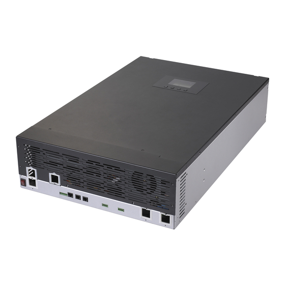
- Page 1 I N V E R T E R INSTALLATION MANUAL H5000 HYBRID INVERTER R e v . 2 © 2 0 1 7 D a r f o n E l e c t r o n i c s C o r p .
-
Page 2: Table Of Contents
I N S T A L L A T I O N M A N U A L H 5 0 0 0 H Y B R I D I N V E R T E R TABLE OF CONTENTS IMPORTANT SAFETY WARNINGS ................... -
Page 3: Important Safety Warnings
I N S T A L L A T I O N M A N U A L H 5 0 0 0 H Y B R I D I N V E R T E R IMPORTANT SAFETY WARNINGS PLEASE READ ALL INSTRUCTIONS AND CAUTIONARY MARKINGS ON THE UNIT AND THIS MANUAL BEFORE USING THE INVERTER. -
Page 4: Introduction
I N V E R T E R INTRODUCTION BASIC HYBRID PV STORAGE SYSTEM OVERVIEW The H5000 hybrid inverter provides power to the essential load by utilizing power from PV panels, the utility and batteries. When the PV panels (two string input) generates enough power, the inverter supports the essential load, feeds back to the grid and charges the batteries, all at the same time. -
Page 5: Mounting The Inverter
Before installation, inspect the unit make sure nothing inside the package is damaged. You should have received the following items in the package: H5000 hybrid inverter and Installation Manual. The following considerations must be taken into account before selecting where to install. - Page 6 I N S T A L L A T I O N M A N U A L H 5 0 0 0 H Y B R I D I N V E R T E R Step 3. Using the mounting bracket as a template and install anchors as needed.
-
Page 7: Grid (Utility) Connect Ion
I N S T A L L A T I O N M A N U A L H 5 0 0 0 H Y B R I D I N V E R T E R GRID (UTILITY) CONNECT ION Preparation Before connecting to the utility, please install a separate AC circuit breaker between inverter and AC Grid utility. -
Page 8: Battery Connection
I N S T A L L A T I O N M A N U A L H 5 0 0 0 H Y B R I D I N V E R T E R BATTERY CONNECTION Preparation Before connecting the batteries, install a separate DC circuit breaker between the inverter and the batteries. -
Page 9: Pv Module (Dc) Connection
Class A-rated. To avoid any malfunction, do not connect any PV modules with possibility of leakage current to the inverter. For example, non-grounded PV modules will cause leakage current to the inverter. CAUTION. To reduce the risk of damage due to surge, Darfon recommends surge protection between the modules and the inverter. -
Page 10: Load (Ac Output) Connection
I N S T A L L A T I O N M A N U A L H 5 0 0 0 H Y B R I D I N V E R T E R LOAD (AC OUTPUT) CONNECTION Preparation To prevent further supply to the load via the inverter during any mode of operation, an additional disconnection device should be placed on in the building wiring installation. -
Page 11: Final Installation Steps
I N S T A L L A T I O N M A N U A L H 5 0 0 0 H Y B R I D I N V E R T E R FINAL INSTALLATION STEPS The wiring for all the connections should be done at this point. -
Page 12: Operation And Display Panel
I N S T A L L A T I O N M A N U A L H 5 0 0 0 H Y B R I D I N V E R T E R OPERATION AND DISPLAY PANEL ICON FUNCTION DESCRIPTION... -
Page 13: System Settings
I N S T A L L A T I O N M A N U A L H 5 0 0 0 H Y B R I D I N V E R T E R System Settings The System settings are divided into two parts, “System Mode Setting” and “System Time Setting.” To get to the ←... - Page 14 To modify the settings for “MULTI-INV” and “BATTERY TYPE” at the bottom of System Setting Page, you will need the factory password. Please contact your Darfon representative. If the password was entered correctly, the display will show a “Setting OK!!”...
-
Page 15: Warning And Fault Definition
I N S T A L L A T I O N M A N U A L H 5 0 0 0 H Y B R I D I N V E R T E R Warning and Fault Definition On the Power Flows Page, the icon will flash when an error has occurred. - Page 16 I N S T A L L A T I O N M A N U A L H 5 0 0 0 H Y B R I D I N V E R T E R On the Power Flows Page, the icon will flash when an overload has occurred.
-
Page 17: Mode Rule Definition
I N S T A L L A T I O N M A N U A L H 5 0 0 0 H Y B R I D I N V E R T E R MODE RULE DEFINITION This hybrid inverter has six modes of operation for backup, residential and time of use. -
Page 18: Aux. Control Port
I N S T A L L A T I O N M A N U A L H 5 0 0 0 H Y B R I D I N V E R T E R AUX. CONTROL PORT On the bottom panel, there are 7 pin for Aux. -
Page 19: Generator Application Schematic
I N S T A L L A T I O N M A N U A L H 5 0 0 0 H Y B R I D I N V E R T E R Generator Application Schematic Generator recommended circuit wiring R e v . -
Page 20: Battery Charging Requirements
The default charging parameters are shown below. Use this as a reference to make sure the battery selected is compatible with H5000 inverter. It is recommended that you use a deep cycle battery when the mode of operation is not set as one of the two back-up modes. If you want to change battery charging parameters, please contact your Darfon representative. -
Page 21: Hardware Connection
I N S T A L L A T I O N M A N U A L H 5 0 0 0 H Y B R I D I N V E R T E R HARDWARE CONNECTION: Connecting to the hardware Step1: Remove the eleven screws on the bottom sides of the inverter. - Page 22 Rx-2 Step 3: Please make sure the jumper pins on Tx-2 and Rx-2. Step 4: The H5000 hybrid inverter need to connect the power, either choices PV, Battery or Grid. Then use the application software setting your parameters. R e v . 2 ©...
-
Page 23: Use Application Software Modifies Parameters
H Y B R I D I N V E R T E R USE APPLICATION SOFTWARE MODIFIES PARAMETERS: Preparation Download the H5000 application software from Darfonsolar website: http://www.darfonsolar.com/downloads/ Connecting to the application software and modifies parameters Step1: Click “HyBridTool” folder Step2: Click “HyBridRDTool”... - Page 24 I N S T A L L A T I O N M A N U A L H 5 0 0 0 H Y B R I D I N V E R T E R Step3: Click “Option”, and select port Step4: Click “Read All Parameter”...
- Page 25 I N S T A L L A T I O N M A N U A L H 5 0 0 0 H Y B R I D I N V E R T E R Step5: Modifies parameters. Step6: Click “one Inverter”, every group has its write one inverter button.
-
Page 26: Parameters Setting Tables
I N S T A L L A T I O N M A N U A L H 5 0 0 0 H Y B R I D I N V E R T E R Parameters setting tables: ■Device: GRID VOLTAGE 0:240V... - Page 27 1: PARALLEL SETTING 2: THREE PHASE 0: NO SETTING 1: LEAD-ACID BATTERY TYPE 2: GLODEN CROWN 3: DARFON GROWATT BATTERY CURRENT 10A ~ 60A MAX BATTERY CHARGING CURRENT BATTERY SHUTDOWN VOLTAGE 44.0V ~ 48.0V BATTERY CUT OFF VOLTAGE BATTERY FLOATING VOLTAGE 54.0V ~ 58.0V...
-
Page 28: Maintenance & Cleaning
I N S T A L L A T I O N M A N U A L H 5 0 0 0 H Y B R I D I N V E R T E R MAINTENANCE & CLEANING Preform the following maintenance annually or more often if the site requires it to ensure proper operation. -
Page 29: Specifications
I N S T A L L A T I O N M A N U A L H 5 0 0 0 H Y B R I D I N V E R T E R SPECIFICATIONS SOLAR DC INPUT Maximum Power 6500W Operation / MPPT Voltage Range... -
Page 30: Grid Support Paramerters
I N S T A L L A T I O N M A N U A L H 5 0 0 0 H Y B R I D I N V E R T E R GRID SUPPORT PARAMERTERS Model(s) H5000 Certificate # UL1741SA Manufacturer Stated Tolerance Value unit Voltage... - Page 31 I N S T A L L A T I O N M A N U A L H 5 0 0 0 H Y B R I D I N V E R T E R FREQUENCY RIDE-THROUGH Trip time DESCRIPTION 0.166 sec Trip time when the frequency is above 62Hz...
-
Page 32: 5-Year Limited Warranty
Darfon’s Return Merchandise Authorization policy and procedure on behalf of the end user. If the original installer cannot be contacted, the end user will need to contact Darfon for a referral to a local authorized installer. This Limited Warranty will be void if the Product is uninstalled and returned by an unauthorized installer. - Page 33 © 2017 Darfon Electronics Corp. All rights reserved. All specifications are subject to change without prior notice. Darfon and the Darfon logo are trademarks of Darfon Electronics Corp. All other trademarks are the property of the respective owners. R e v . 2 ©...
Need help?
Do you have a question about the H5000 and is the answer not in the manual?
Questions and answers