Table of Contents
Advertisement
Q u i c k I n s t a l l a t i o n G u i d e
IMPORTANT SAFETY WARNINGS
PLEASE READ ALL INSTRUCTIONS AND CAUTIONARY MARKINGS ON THE UNIT AND THIS GUIDE BEFORE INSTALLING THE INVERTER.
AND, STORE THIS USER MANUAL WHERE IT CAN BE ACCESSED EASILY.
This manual is for qualified personnel. The tasks described in this manual should be performed by qualified personnel only.
Safety Symbols
WARNING. This indicates the risk of electric shock. The presence of high voltage levels may constitute a risk of injury or death to users
and/or installers.
CAUTION. This indicates important information where failure to comply may result in safety hazards or cause damage to this product.
General Precautions
CAUTION. Before installing and using this inverter, read all instructions and cautionary markings on the inverter and all appropriate
sections of this guide. Installing this inverter by licensed electricians only.
CAUTION. Normally grounded conductors may be ungrounded and energized when a ground fault is indicated.
CAUTION. This inverter is heavy. It should be lifted by at least two persons for the safety.
WARNING. Authorized service personnel should reduce the risk of electrical shock by disconnecting AC, DC and battery power from
the inverter before attempting any maintenance or cleaning or working on any circuits connected to the inverter. Turning off controls
will not reduce this risk. Internal capacitors can remain charged for 5 minutes after disconnecting all sources of power.
WARNING. Do not disassemble this inverter yourself. It contains no user-serviceable parts. Attempt to service this inverter yourself may
cause a risk of electrical shock or fire and will void the warranty from the manufacturer.
WARNING. To avoid a risk of fire and electric shock, make sure that existing wiring is in good condition and that the wire is not
undersized. Do not operate the Inverter with damaged or substandard wiring.
WARNING. To reduce risk of fire hazard, do not cover or obstruct the cooling fans.
CAUTION. Do not install the Inverter if it has received a sharp blow, been dropped, or otherwise damaged in any way. If the Inverter is
damaged, call for an RMA (Return Material Authorization).
CAUTION. This inverter is not allowed to operate in parallel. Do not parallel connect more than one unit in AC output connector.
Otherwise, it will damage this inverter.
Manufactured by
Darfon Electronics Corp.
167 Shan-ying Road, Gueishan
Taoyuan 333, Taiwan, (R.O.C.)
Tel: +886 3 2508800
©2018 Darfon Electronics Corp. All rights reserved. All specifications are subject to change without prior notice. Darfon and the Darfon logo are trademarks of Darfon
Electronics Corp. All other trademarks are the property of the respective owners.
WHAT'S IN THE BOX
2
1
4
R e v . 1
USA Office
Darfon America Corp.
103A Pioneer Way
Mountain View, CA 94041
Tel: +1.650.316.6300
3
5
© 2 0 1 8 D a r f o n E l e c t r o n i c s C o r p .
H B 5 1 H y b r i d I n v e r t e r
For more information
www.darfonsolar.com
Parts Description
Qty
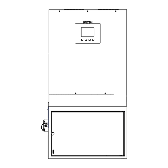
1. HB51 Inverter
2. Backplate
3. Bracket
4. Wood Screws
5. Self-drilling Screws
1
1
2
6
6
1 | P a g e
Advertisement
Table of Contents

Related Manuals for Darfon HB51


Summary of Contents for Darfon HB51
- Page 1 Tel: +886 3 2508800 Tel: +1.650.316.6300 ©2018 Darfon Electronics Corp. All rights reserved. All specifications are subject to change without prior notice. Darfon and the Darfon logo are trademarks of Darfon Electronics Corp. All other trademarks are the property of the respective owners.
-
Page 2: Product Overview
Q u i c k I n s t a l l a t i o n G u i d e H B 5 1 H y b r i d I n v e r t e r PRODUCT OVERVIEW Communication Ports RJ45... -
Page 3: Mounting The Inverter
Q u i c k I n s t a l l a t i o n G u i d e H B 5 1 H y b r i d I n v e r t e r MOUNTING THE INVERTER Notes Mounting Dimensions... - Page 4 Q u i c k I n s t a l l a t i o n G u i d e H B 5 1 H y b r i d i n v e r t e r CONNECTIONS Notes Wire/Cable Requirements...
-
Page 5: Wiring Diagram
H B 5 1 H y b r i d i n v e r t e r WIRING DIAGRAM Grid KWH Meter PV Panels Main Utility Panel HB51 Inverter Grid Terminals Micro Inverters Battery Terminals Load Terminals Essential Load Panel... -
Page 6: Turning Off The System
Q u i c k I n s t a l l a t i o n G u i d e H B 5 1 H y b r i d i n v e r t e r TURNING OFF THE SYSTEM 1. -
Page 7: Changing The Mode Of Operation
Q u i c k I n s t a l l a t i o n G u i d e H B 5 1 H y b r i d i n v e r t e r CHANGING THE MODE OF OPERATION 1. -
Page 8: Setting Battery Type
Battery Type. to select it. BATTERY TYPE None Lead-Acid Golden Crown Darfon LNMC Panasonic Darfon LFP 4. You will see a message stating the 5. When you see “Setting OK!!” 6. Manually restart the inverter using settings are being updated.
Need help?
Do you have a question about the HB51 and is the answer not in the manual?
Questions and answers