INIM Electronics Air2 Installation And Programming Manual
Wireless devices
Hide thumbs
Also See for Air2:
- Installation and programming manual (12 pages) ,
- Installation and programming manual (16 pages) ,
- Installation and programming manual (16 pages)

Related Manuals for INIM Electronics Air2


Summary of Contents for INIM Electronics Air2
- Page 1 Installation and programming manual EN 50131-1 EN 50131-5-3 EN 50130-4 EN 50130-5 Air2 Wireless devices Installation and programming manual...
-
Page 2: Table Of Contents
Air2-BS200 address ........13... -
Page 3: Chapter 1 General Information
Web: www.inim.biz The persons authorized by the manufacturer to repair or replace the parts of this system, hold authorization to work on INIM Electronics brand devices only. System Description The advanced Air2 two-way wireless intrusion protection system (868MHz frequency) integrates directly with all models in INIM intrusion control panel range. -
Page 4: Notes From The Manufacturer
The notified body N°0051, intervened in the R&TTE Directive conformity assessment procedure for all the devices of the Air2 system, with the exception of the Air2-FD100 and Air2-MC200. The information relating to the power-supply batteries required by Air2 devices is shown in the Technical Specification table that follows. -
Page 5: Description Of Products
10 expansion boards, at addresses ADD, ADD+1, ... ADD+9, capable of managing the terminals. Additionally, each Air2-BS200 allows the SmartLiving control panel to manage up to 4 Aria wireless keypads and 4 Hedera wireless sounders. Table 3: Technical specifications of the Air2-BS200... -
Page 6: Air2-Ir100 And Air2-Ir100/C Pir Detectors
(accepted value between 1 and 4) from the keypad or EN 50131-5-3 through the SmartLeague software application. EN 50131-2-2 The Air2-IR100/C PIR detector has the same features as the Air2-IR100 but EN 50130-4 covers a greater distance (20m) with a minor angle. EN 50130-5... - Page 7 Installation and programming manual Table 7: Description of Air2-IR100 parts Battery Air2-IR100 - Backbox Antenna Air2-IR100 - Signalling LED - red PIR detector Open-tamper microswitch ENROLL microswitch Mounting screw hole Tamper screw hole Enclosure screw hole VOLUMETRIC The following volumetric-coverage diagrams refer to detectors whose sensitivity is set by the control panel at maximum sensitivity.
-
Page 8: Air2-Mc100 Magnetic Contact
Wireless accessories Air2-MC100 magnetic contact The Air2-MC100 magnetic contact has two screw-in positions for placement optimization of the device magnet, 90° one from the other. It also provides Alarms two terminals which can be configured as inputs or open- collector outputs. Configuring the terminals as inputs provides standard zone management (NO, NC, Single Balancing, Double Balancing) and allows direct connection to rollerblind sensors. -
Page 9: Air2-Mc200 Magnetic Contact
Air2-MC200 magnetic contact The Air2-MC200 is supplied with a magnet which is to be secured (by means of two EN 50131-1 screws) to the side of the contact, in the position indicated by the two notches. -
Page 10: Air2-Kf100 Remote-Control Keyfob
Air2-KF100 remote-control keyfob The Air2-KF100 keyfob has 4 button which can be programmed from the control panel. EN 50131-1 The graphic-choice feature allows you to identify the buttons by numbers or icons. -
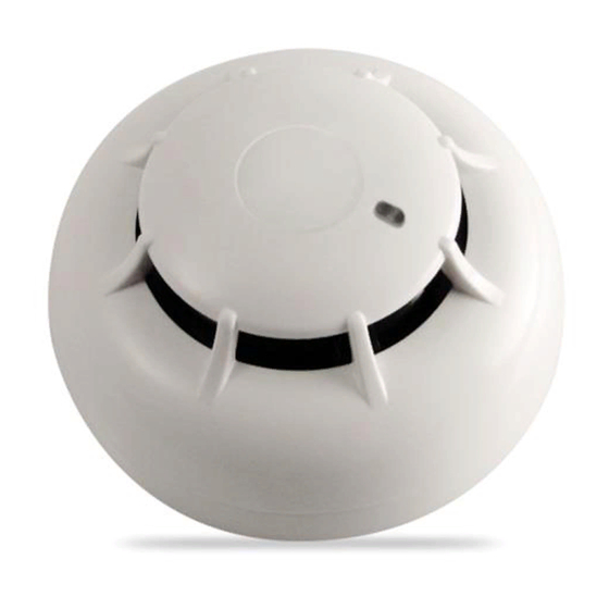
Page 11: Air2-Fd100 Smoke Detector
ATTENTION! The sole task of the Air2-FD100 smoke detector is to sense for smoke in the protected area. Therefore, in no way can the combination of a SmartLiving system and an Air2-FD100 smoke detector be considered a fire control system. - Page 12 Wireless accessories Table 19: Description of Air2-FD100 parts Detector LED red/yellow/green Optical chamber Battery Tamper microswitch ENROLL microswitch Base Mounting screw hole The tricolour LED (360° visibility) indicates the detector status. • Green - one flash every 15 seconds: detector not operating properly.
-
Page 13: Chapter 3 Operating Principles
Chapter 3 OPERATING PRINCIPLES Air2-BS200 address In order to configure the Air2-BS200 in the control panel it is necessary to assign an address between 1 and 30 (to set the address follow the instructions in paragraph 4-6 Addressing the Air2-BS200). -
Page 14: Chapter 4 Installation
Hold the base to the chosen mounting placement and mark the screw holes and tamper protection position. Pull the wires through the cable entry and wire up the Air2-BS200. Using the screws, secure the base and the tamper protection in position. -
Page 15: Installing The Air2-Mc200
Re-attach the cover to the base of the contact and replace the enclosure screw. Installing the Air2-KF100 The Air2-KF100 requires enrolling only. If it becomes necessary to replace the device cover or battery, work through the following steps. Remove the enclosure screw on the back of the keyfob and open the device. -
Page 16: Addressing The Air2-Bs200
Wireless accessories Addressing the Air2-BS200 The address (“ADD”) to be assigned to the Air2-BS200 transceiver must be the same as the address of the simulated reader. The address assignment phase takes place during programming phase 6 of the module (refer to paragraph 5-2 Programming via the Air2-BS200 module). During... -
Page 17: Enrolling The Devices
Magnetic contact, allows you to enroll Air2-MC100 magnetic reed con- tact • Terminal T1 M.C., allows you to enroll the “T1” terminal of an Air2- MC100 • Terminal T2 M.C., allows you to enroll the “T2” terminal of an Air2- MC100 •... -
Page 18: Chapter 5 Programming
5 wireless keyfobs Minimum requirements: 18/5=4 expansion boards; if the 2 expansion boards are for the hardwired zones assign them to addresses 1 and 2; set the Air2-BS200 DIP-microswitches to address 3 (LED DL1 Off, DL2 Off, DL3 On, DL4 On). -
Page 19: Air2-Bs200 Module Default Settings
The red LED of Air2-IR100 and MC200 devices signal alarm or tamper on the Air2-MC100/MC200 devices is device. always Off. ATTENTION! Use sensor LED In the case of an Air2-MC100 device, this option should be enabled on all its terminals. Programming... - Page 20 Accepted values: 12 to 250 minutes (30 minutes at default). • Disable tamp. WLS - If this option is disabled, open/dislodgement tamper on Air2 devices will not generate the respective events. Programming...
-
Page 21: Appendix A Declaration Of Conformity Of The Air2-Bs200
1999/5/EC. Islenska: Hér með lýsir INIM Electronics yfi r því að Air2-BS200 er í samræmi við grunnkröfur og aðrar kröfur, sem gerðar eru í tilskipun 1999/5/EC. -
Page 22: Appendix B Order Codes
Air2-XIR200W Wireless dual-technology PIR detector - 12m DCMIINE0A2BS200E Air2 devices installation manual Intrusion control panel: manages 10 to 100 terminals, 15 partitions, switching power supply @5A, SmartLiving10100L optional TCP/IP connectivity, comes in metal enclosure with housing for 1 battery @17Ah... - Page 23 Installation and programming manual Notes...
- Page 24 Wireless devices ISO 9001 Quality Management certified by BSI with certificate number FM530352 via Fosso Antico snc - fraz. Centobuchi 63076 Monteprandone (AP) ITALY Tel. +39 0735 705007 _ Fax +39 0735 704912 info@inim.biz _ www.inim.biz...
Need help?
Do you have a question about the Air2 and is the answer not in the manual?
Questions and answers