Table of Contents
Advertisement
Quick Links
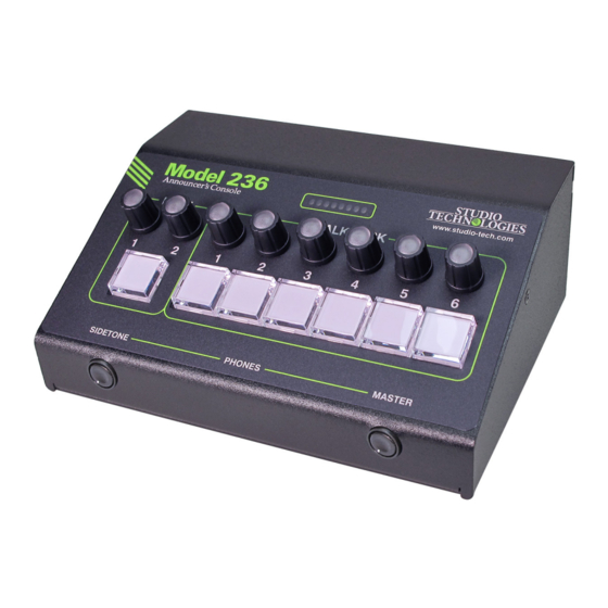
Model 236
Announcer's Console
User Guide
Issue 6, March 2022
This User Guide is applicable for serial numbers
M236-00151 and later with Main Firmware version 3.03 and later
and STcontroller software application version 3.08.00 and later
Copyright © 2022 by Studio Technologies, Inc., all rights reserved
studio-tech.com
50688-0322, Issue 6
Advertisement
Table of Contents

Related Manuals for Studio Technologies 236


Summary of Contents for Studio Technologies 236
- Page 1 This User Guide is applicable for serial numbers M236-00151 and later with Main Firmware version 3.03 and later and STcontroller software application version 3.08.00 and later Copyright © 2022 by Studio Technologies, Inc., all rights reserved studio-tech.com 50688-0322, Issue 6...
- Page 2 This page intentionally left blank.
-
Page 3: Table Of Contents
Table of Contents Revision History ......................4 Introduction ........................ 5 Getting Started ......................7 Dante Configuration ....................9 Model 236 Configuration ................... 11 Operation ........................19 Technical Notes ......................26 Specifications ......................31 Appendix A: STcontroller Default Configuration Values ..........33 Appendix B: 3-Pin Header Connector Details ............ -
Page 4: Revision History
Adds technical note regarding level attenuation in Dante Aux and Talkback transmitter (output) channels when Analog Mic Output is configured for Switched. Issue 1, August 2020: • Initial release. Issue 6, March 2022 Model 236 User Guide Page 4 Studio Technologies, Inc. -
Page 5: Introduction
“customizing” the operation the range of operating capabilities includes the ability to of a Model 236 fast and simple. The unit’s ability to han- create talent cue (IFB) channels. This was specifically dle both day-to-day and specialized situations makes it included for REMI/At-Home applications. - Page 6 (digital and analog) as well as Dante Audio-over-Ethernet the six talkback functions. Extensive configuration choices Audio data is sent to and received from the Model 236 using allow the operation of the pushbutton switches and associ- Dante audio-over-Ethernet media networking technology.
-
Page 7: Getting Started
Contact closures can be interfaced to the Model 236’s cir- The Model 236 was designed so that in the future its capa- cuitry, allowing external switches to activate the main and bilities and performance can be easily enhanced. A USB talkback functions. - Page 8 An external source of 12 volts DC can be connected to the piece of equipment is already providing microphone power. Model 236 by way of a 4-pin male XLR connector which is This input could be connected to the Model 236 by way of located on the unit’s back panel.
-
Page 9: Dante Configuration
The Dante Configuration output signals from an I/O interface’s preamplifier channels For audio to correctly pass to and from the Model 236 are typically transported to the main electronics or console requires, at a minimum, that several Dante-related surface using a fiber optic interface. - Page 10 ANNOUNCER’S CONSOLE Using Dante Controller, the desired Dante transmitter (out- Dante devices. If both of the Model 236’s RJ45 connec- put) sources can be routed to the eleven Dante receiver tions are routed to ports on the same LAN this will typically (input) channels associated with the Model 236.
-
Page 11: Model 236 Configuration
Model 236 Configuration The Studio Technologies’ STcontroller software applica- tion is used to configure the way in which the Model 236 functions. No DIP switch settings or other local actions are used to configure the unit. This makes it imperative that STcontroller be available for convenient use on a personal computer that’s connected to the related LAN. - Page 12 STcontroller and by way of an orange LED that is located when it is utilized by the main and talkback output channels. on the Model 236’s back panel adjacent to the analog Off: When selected, no limiter action will take place.
- Page 13 An eight-LED dual-color multi-purpose display is provided indication of when the limiter function is actively controlling on the front panel of the Model 236. It can display the level the signal level. The level meter will typically be used as of the selected microphone input source.
- Page 14 Switched and Always On. tion (“color blindness”) the main pushbutton switch can be On the Model 236’s back panel is a 3-pin male XLR con- configured to not light when the function is off (not active). nector that is labeled Mic Out. The way in which this output...
- Page 15 I/O interface) then the in the Model 236’s back panel. Refer to the Technical Notes Model 236’s analog microphone input P48 phantom power section for details.
- Page 16 The Upon Model 236 power up the main button will be in its end of each knob will flash purple five times to indicate that inactive state and its red LED will be lit.
- Page 17 A configuration choice allows the signal that arrives on the press will impact the ability to monitor the talkback source. Model 236’s Dante Talkback receiver (input) channel to be routed to the left channel, right channel, or both the left...
- Page 18 This might be appropriate if a It is intended for use in REMI/At-Home applications where Model 236 is being used as an intercom station or in a a “pilot tone” needs to be sent along with microphone audio.
-
Page 19: Operation
(IFB) function to be created direct- nels are associated with the Main and Talkback functions. ly inside the Model 236. This can be very useful in REMI/ Another Dante transmitter (output) channel is associated At-Home applications where there may not be a central with the Model 236’s Aux output. - Page 20 (timing reference) is being received. It will slowly active. For applications where the user may have trouble flash green when this specific Model 236 is part of a Dante identifying the difference between the colors green and red Issue 6, March 2022...
- Page 21 “eyeball” icon that when clicked will activate the Model a microphone signal level that’s within the normal range. 236’s Identify function. On that unit the eight LEDs asso- The next two LEDs (6 and 7) will light orange when a ciated with the front-panel multi-purpose display will flash microphone signal level is greater than normal.
- Page 22 (summed) with the audio present on an active not pressed and disabled when the button is pressed. Model 236 talkback channel that is configured to either the This is a typical “cough” function that’s frequently utilized Talk or the Talk with 18 kHz Tone modes.
- Page 23 Always, will be appropriate. This mode will allow an audio rotary potentiometer, located on the right side of the Model source entering the Model 236 by way of a Dante Talkback 236’s front panel and labeled Master, is used to adjust the receiver (input) channel to always be able to be monitored.
- Page 24 Main Receiver Rotary Encoders Model 236 can indicate the approximate position of each A single rotary encoder is associated with the left and right rotary encoder. Each LED on the multi-purpose display will input channels of Main Input 1.
- Page 25 Whenever mute is active any changes to a rotary encoder’s Tone Detect Function position will not be recognized. The Model 236 can be configured to respond to a high- As previously mentioned, 32 encoder steps (1 and 1/3 frequency tone signal that is present in a Dante Talkback rotation of a rotary encoder knob) are required to move receiver (input) channel.
-
Page 26: Technical Notes
DC output that is active whenev- Optimizing Network Performance er the Model 236’s main function is active. This is intended For best Dante audio-over-Ethernet performance a network to serve as an on-air tally output to directly light an LED or that supports VoIP QoS (voice-over-internet-protocol quality activate an input on another piece of equipment. - Page 27 Ensure have a recommended method as to how to install custom that the flex cable is not damaged while the Model 236 is labels underneath the button caps. We have observed being customized.
- Page 28 The headers are Molex part number 22-23-2031. They ® Model 236 is very simple. If a tone is detected on the audio mate with Molex housing number 22-01-3037. To make signal arriving on a Dante Talkback receiver (input) the the interconnection, separate crimp terminals are attached tone detect function will respond by attenuating (dimming to three loose wires and then “snapped”...
- Page 29 The speed at which the limiter is no longer active (the “release time”) loaded into a Model 236 at the same time. In the flash is much longer. The gain reduction will be maintained for drive’s root folder, save the desired new firmware file(s)
- Page 30 Model 236’s required by the Model 236, the name of the zip file itself three firmware files are as expected. This is easily will include the file’s version number.
-
Page 31: Specifications
Threshold: 12 dB above nominal level (–8 dBFS) Minimum On Time: 30 milliseconds Maximum Attenuation: 16 dB at 36 dB or greater microphone preamplifier gain Model 236 User Guide Issue 6, March 2022 Studio Technologies, Inc. Page 31... - Page 32 Analog Microphone Input: 3-pin header located on the analog circuit board Spare Connector Locations: 2 Allows a Studio Technologies’ cable assembly or option module to be installed. Also compatible with Neutrik NC*D-L-1 connectors (*=3F, 3M, 5M, 6F, 6FS, etc.). Configuration: requires Studio Technologies’...
-
Page 33: Appendix A: Stcontroller Default Configuration Values
Talkback – Listen Mode: Always Talkback – Button Mode: Hybrid Talkback – Button Function: Talk Talkback – Impact on Main Output: Mutes Talkback – Tone Detect Function: None Model 236 User Guide Issue 6, March 2022 Studio Technologies, Inc. Page 33... -
Page 34: Appendix B: 3-Pin Header Connector Details
ANNOUNCER’S CONSOLE Appendix B: 3-Pin Header Connector Details The following list provides details on the 3-pin header connectors located on the Model 236’s printed circuit boards. Shown are both reference numbers and associated functions. I. Header on the Analog Board:... -
Page 35: Appendix C: Block Diagram
Model 236 ANNOUNCER’S CONSOLE Appendix C: Block Diagram The following block diagram shows a simplified version of the microphone input and microphone output circuitry. Model 236 User Guide Issue 6, March 2022 Studio Technologies, Inc. Page 35...
Need help?
Do you have a question about the 236 and is the answer not in the manual?
Questions and answers