Advertisement
Quick Links
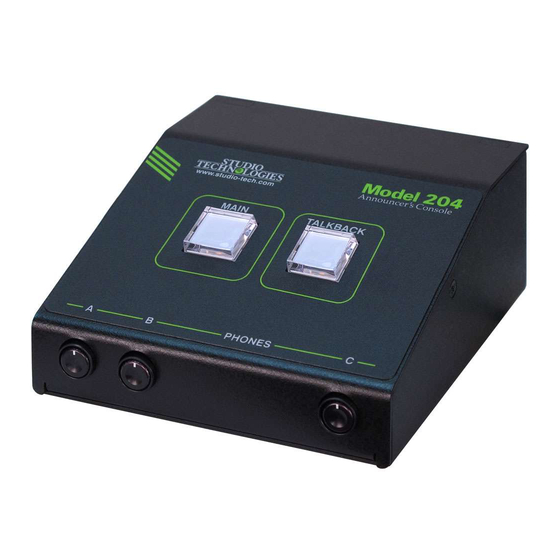
Model 204 Announcer's Console
User Guide
Issue 2, October 2018
This User Guide is applicable for serial numbers
M204-00151 to 00500 with application firmware 1.2 and later
and STcontroller application version 1.07.00 and later.
Copyright © 2018 by Studio Technologies, Inc., all rights reserved
www.studio-tech.com
50639-1018, Issue 2
Advertisement

Related Manuals for Studio Technologies 204


Summary of Contents for Studio Technologies 204
- Page 1 Issue 2, October 2018 This User Guide is applicable for serial numbers M204-00151 to 00500 with application firmware 1.2 and later and STcontroller application version 1.07.00 and later. Copyright © 2018 by Studio Technologies, Inc., all rights reserved www.studio-tech.com 50639-1018, Issue 2...
- Page 2 This page intentionally left blank.
-
Page 3: Table Of Contents
Revision History ............4 Introduction ..............5 Getting Started ............. 10 Operation ..............19 Technical Notes ............24 Specifications ............... 28 Appendix A: Model 204 Block Diagram ......29 Model 204 User Guide Issue 2, October 2018 Studio Technologies, Inc. Page 3... -
Page 4: Revision History
Revision History Issue 2, October 2018: • Documents addition of the Push to Mute/Tap to Latch main button operating mode. Issue 1, May 2018: • Initial release. Issue 2, October 2018 Model 204 User Guide Page 4 Studio Technologies, Inc. -
Page 5: Introduction
Applications sports, eSports, live event, entertainment, and streaming broadcast applications. The The Model 204 on its own can provide an unit is housed in a compact, rugged steel “all-Dante” solution for one on-air talent enclosure that’s intended for table-top location. - Page 6 Set up, configuration, and operation of Dante output channel which makes routing the Model 204 is simple. An etherCON® to an input on a variety of devices, such as RJ45 jack is used to interconnect with a...
- Page 7 Ethernet Data and PoE AES67 interoperability standard. In this mode the two transmitter (output) channels The Model 204 connects to a local area will function in multicast; unicast is not sup- network (LAN) by way of a standard 100 ported. In addition, the unit is compatible Mb/s twisted-pair Ethernet interface.
- Page 8 Configuration choices allow Configuration Flexibility these to be assigned to work in paral- The Model 204 can be configured to meet lel with the main or talkback pushbutton the needs of specific applications and user switches. In this way activation of a remote preferences.
- Page 9 Model control the level of a stereo input signal 204 by way of Dante inputs 1 and 2 and as it is routed to the left and right chan- is routed in stereo to the left and right nels of the headphone output.
-
Page 10: Getting Started
ANNOUNCER’S CONSOLE Three system modes select the overall An Ethernet data connection with Power- way in which the Model 204 functions. The over-Ethernet (PoE) capability will be on-air mode is optimized for applications made using either a standard RJ45 patch... - Page 11 This could be connected to the current draw. To prevent this undesirable Model 204 by way of the microphone output condition ensure that no input audio signal connector. This would not create a problem...
- Page 12 Refer to Appendix A for a A 3.5 mm 3-conductor jack is located on block diagram of the microphone input and the Model 204’s back panel and provides microphone output circuitry. access to the two remote control inputs.
- Page 13 4-output integrated circuit to implement KHz will be appropriate. While technically the Dante functionality. The Model 204 the Model 204 can serve as a clock master can also be configured to meet the re- for a Dante network (as can all Dante- quirements of the AES67 standard.
- Page 14 LED, orange in color Windows operating systems that are and visible on the back of the Model 204’s version 7 and later. STcontroller versions enclosure adjacent to the microphone 1.07.00 and later will fully support the Mod- input connector, can act as a guide when el 204.
- Page 15 In these pot B adjusts its level. A stereo pair can applications it’s typical to want the user to enter the Model 204 by way of Dante input have a single potentiometer to simultane- channels 3 and 4. These signals, whose...
- Page 16 Dante input channels. But if “mix-minus” au- lized Dante input channels will always be dio is being supplied to the Model 204 then present on the headphone output. In most selecting a headphone source and routing...
- Page 17 Dante output channel and Upon Model 204 power up the main the microphone output connector. In ad- button will be in its inactive state and its dition, the button’s green LED will light.
- Page 18 Upon buttons to be used simultaneously. When Model 204 power up the talkback button selected for the correct application, the pro- will be in its inactive state and its LED duction mode can prove to be very useful.
-
Page 19: Operation
The intensity Initial Operation of these LEDs can be adjusted to meet the The Model 204 will start to function as soon needs of an application, specifically being as a Power-over-Ethernet (PoE) power configured to perform optimally vis-à-vis source is connected. - Page 20 (timing reference) is being Model 204 received. It will slowly flash green when this specific Model 204 is part of a Dante Functions within the Dante Controller and network and is serving as the clock mas- STcontroller software applications allow ter.
- Page 21 Dante microphone output connector that’s located main output channel and the microphone on the back panel of the Model 204. How output connector will alternate between the button functions will depend on the the active and muted states whenever configuration choice that has been made the main pushbutton is pressed.
- Page 22 MODEL 204 ANNOUNCER’S CONSOLE • Push to Mute/Tap to Latch: This mode is Upon Model 204 power up the audio sig- a combination of the Push to Mute and nals on the Dante talkback output chan- Latching modes. Whenever the main nels will be in their muted state.
- Page 23 The three rotary potentiometers (pots), main button will be forced to be inactive located on the Model 204’s front panel, whenever the talkback function is active. allow level adjustment of the Dante au-...
-
Page 24: Technical Notes
Private IP Addressing (APIPA). It is also In the unfortunate event that a specific sometimes referred to as auto-IP (PIPPA). Model 204’s IP address is “lost,” the Ad- Link-local will randomly assign a unique IP dress Resolution Protocol (ARP) network- address in the IPv4 range of 169.254.0.1... - Page 25 1.2 is present in the to the naming convention required by the Model 204. Model 204, the name of the zip file itself will A selection in the STcontroller software include the file’s version number. For exam- application allows the Model 204’s ap-...
- Page 26 At this point the file will automatically newly-loaded application firmware. load. The precise steps required will be 6. At this time the Model 204 is function- highlighted in the next paragraphs of this ing with the newly-loaded application guide.
- Page 27 Audinate. The Dante Con- A command in the STcontroller software troller software application can be used application allows the Model 204’s defaults to determine the version of the firmware to be reset to the factory values. From...
-
Page 28: Specifications
Impedance: 3.1 k ohms, nominal Ethernet: Neutrik etherCON RJ45 Gain: 35, 43, 52, 59 dB, selectable USB: type A receptacle (located inside Model 204’s Frequency Response: 25 Hz to 20 kHz, –3 dB enclosure and used only for updating firmware) Distortion (THD+N): <0.018%, measured at 35 dB... -
Page 29: Appendix A: Model 204 Block Diagram
MODEL 204 ANNOUNCER’S CONSOLE Appendix A: Model 204 Block Diagram The following block diagram shows a simplified version of the Model 204’s microphone input and microphone output circuitry. Model 204 User Guide Issue 2, October 2018 Studio Technologies, Inc. Page 29...
Need help?
Do you have a question about the 204 and is the answer not in the manual?
Questions and answers