Table of Contents
Advertisement
Quick Links
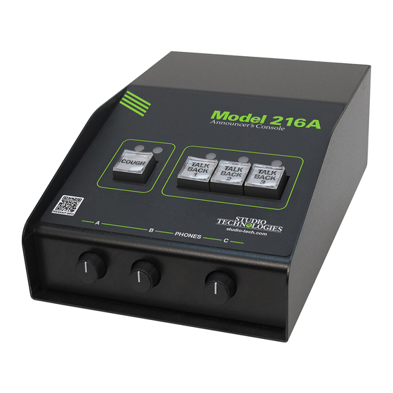
Model 216A
Announcer's Console
User Guide
Issue Preliminary 1, October 2022
This User Guide is applicable for serial numbers
M216A-00151 and later with Main Firmware version 1.00 and later
and STcontroller software application version 3.08.00 and later
Copyright © 2022 by Studio Technologies, Inc., all rights reserved
studio-tech.com
50735-1022, Issue P1
Advertisement
Table of Contents

Related Manuals for Studio Technologies 216A


Summary of Contents for Studio Technologies 216A
- Page 1 This User Guide is applicable for serial numbers M216A-00151 and later with Main Firmware version 1.00 and later and STcontroller software application version 3.08.00 and later Copyright © 2022 by Studio Technologies, Inc., all rights reserved studio-tech.com 50735-1022, Issue P1...
- Page 2 This page intentionally left blank.
-
Page 3: Table Of Contents
Table of Contents Revision History ......................4 Introduction ........................ 5 Getting Started ......................8 Dante Configuration ....................10 Model 216A Configuration ..................11 Operation ........................16 Technical Notes ......................20 Specifications ......................24 Appendix A: STcontroller Default Configuration Values ..........26 Appendix B: 3-Pin Header Connector Details ............ -
Page 4: Revision History
Model 216A ANNOUNCER’S CONSOLE Revision History Issue Preliminary 1, October 2022: • Initial preliminary release. Issue Preliminary 1, October 2022 Model 216A User Guide Page 4 Studio Technologies, Inc. -
Page 5: Introduction
LEDs. Three rotary controls allow the user to adjust the content and level of the headphone output A large part of the Model 216A’s unique power is the ability channels. to configure the operation of the main and talkback func- tions. - Page 6 IFB signals to be created. The Model disable operation. 216A can serve as an IFB main station while the Model The three pushbutton switches associated with the talkback 5422A, located at the event site, will perform the switching...
- Page 7 Dante receiver (input) channel 2 as it is sent to the right headphone output channel. Rotary control B provides the Audio data is sent to and from the Model 216A using the same function for Dante receiver (input) channels 3 and 4.
-
Page 8: Getting Started
If both sources are connected, a Model 216A to be optimized to meet the needs of spe- PoE will power the unit. Four LEDs, located on the back cific applications. For example, some applications may... - Page 9 26-II and HMD 27 headsets are popular for on-air sports Ethernet Connection broadcasting use. Fine products, they work very well with the Model 216A. Adding the suffix “-XQ” to the headsets’ full An Ethernet connection that supports 100BASE-TX is part number specifies a 3-pin male XLR connector for the required for the Model 216A’s Dante audio-over-Ethernet...
-
Page 10: Dante Configuration
12 volts, correct operation will using finger-pressure only. No tool is required to replace take place over a range of 10 to 18 volts. The Model 216A’s the cap. operating current is modest (less than 300 milliamperes) and the exact value is stated in the Specifications section. -
Page 11: Model 216A Configuration
Dante personal computer must be on the same local area network Controller are typically correct. (LAN) and subnet as the Model 216A unit that is going to be configured. Immediately after starting STcontroller the Network Configuration – Address application will locate all the Studio Technologies’... - Page 12 Dante reference level STcontroller allows selection of the on/off status of the which Studio Technologies considers to be –20 dBFS (this microphone input’s P48 phantom power source. The on/ is 20 dB below the digital maximum of 0 dBFS). Operating...
- Page 13 A dual-color LED, located on the Model 216A’s back panel Mode 3 – Ch1 L Ch2 R / Ch3 L Ch4 R / Sidetone LR: This...
- Page 14 (input) channels. But if “mix-minus” audio is being supplied or its fully clockwise position will cause the associated sig- to the Model 216A then selecting one of the headphone nal to mute. Selecting the Full Mute mode may be appropri-...
- Page 15 Upon The operating mode configures the overall manner in Model 216A power up the main button function will be in which the Model 216A operates. Specifically, it determines its inactive state.
-
Page 16: Operation
Again, this mode is specifically included to allow the Model is active. 216A to function as an IFB main station when used in con- junction with the Studio Technologies Model 5422A Dante Main and Talkback Buttons: When relay output 1 is config- Intercom Audio Engine’s tone operated (TOX) IFB function. - Page 17 (timing reference) is being received. It will slowly light on and off green when the Model 216A is part of a Main Button and LED Indicators Dante network and is serving as the Leader clock. (This...
- Page 18 To clarify, when the Model 216A is set to one of the signal associated with the Dante main transmitter (output) production modes, the red LED will never light;...
- Page 19 (50%) position of its rotation range. sidetone function can be active will depend on the con- This is intended to serve as an aid to Model 216A users. In figuration of the Headphone Output – Audio Sources and an ideal installation, setting the controls to their detent posi- Routing parameter in the STcontroller software application.
-
Page 20: Technical Notes
A USB type A receptacle and associated status LED is are optimized for entertainment-associated applications. located on the back panel of the Model 216A. It is labeled Refer to the Audinate website (audinate.com) for details Firmware Update and is used only for updating the unit’s on optimizing networks for Dante applications. - Page 21 Model 216A’s circuit board. These headers, on 0.1-inch relay contacts for use in specialized applications. The action centers, are wired in parallel with some of the Model 216A’s of each can be configured using the STcontroller software connectors. This “no solder” solution makes customizing application.
- Page 22 (A pair of needle-nose pliers or 3. Apply power to the Model 216A. Power can be provid- tweezers may be required to perform this task.) ed by Power-over-Ethernet (PoE) associated with a...
- Page 23 Model 216A unit for which you want to restore its defaults. Select the Device tab and then select the Factory Defaults feature. Then click on the OK box. Refer to Appendix A for a list of the Model 216A’s factory default values. Model 216A User Guide Issue Preliminary 1, October 2022 Studio Technologies, Inc.
-
Page 24: Specifications
Sample Rates: 44.1 or 48 kHz Use: provides support for tone operated (TOX) IFB Pull Up/Down Support: none function on devices such as Studio Technologies’ Dante Transmitter (Output) Channels: 4 (Main, Model 5422A Dante Intercom Audio Engine Talkback 1, Talkback 2, Talkback 3) - Page 25 8.5 inches deep (21.6 cm) Deployment: intended for tabletop applications Weight: 2.4 pounds (1.1 kg) Specifications and information contained in this User Guide subject to change without notice. Model 216A User Guide Issue Preliminary 1, October 2022 Studio Technologies, Inc. Page 25...
-
Page 26: Appendix A: Stcontroller Default Configuration Values
Button Operation – Talkback 3: Push to Talk System – Operating Mode: On Air System – Button Backlight Intensity: Low System – Relay Output 1: Off System – Relay Output 2: Off Issue Preliminary 1, October 2022 Model 216A User Guide Page 26 Studio Technologies, Inc. -
Page 27: Appendix B: 3-Pin Header Connector Details
Model 216A ANNOUNCER’S CONSOLE Appendix B: 3-Pin Header Connector Details The following list provides details on the 3-pin header connectors located on the Model 216A’s printed circuit board. Shown are both reference numbers and associated functions. P2: Microphone Input Pin 1: Common Pin 2: High (+) Pin 3: Low (–)
Need help?
Do you have a question about the 216A and is the answer not in the manual?
Questions and answers