Table of Contents
Advertisement
Quick Links
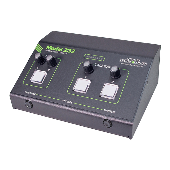
Model 232 Announcer's Console
User Guide
Issue 1, August 2020
This User Guide is applicable for serial numbers
M232-00151 and later with main firmware version 1.02 and later
and STcontroller application version 2.10.00 and later.
Copyright © 2020 by Studio Technologies, Inc., all rights reserved
www.studio-tech.com
50684-0820 Issue 1
Advertisement
Table of Contents

Related Manuals for Studio Technologies 232


Summary of Contents for Studio Technologies 232
- Page 1 Issue 1, August 2020 This User Guide is applicable for serial numbers M232-00151 and later with main firmware version 1.02 and later and STcontroller application version 2.10.00 and later. Copyright © 2020 by Studio Technologies, Inc., all rights reserved www.studio-tech.com 50684-0820 Issue 1...
- Page 2 This page intentionally left blank.
-
Page 3: Table Of Contents
Technical Notes ................31 Specifications ................. 37 Appendix A: STcontroller default configuration values ....39 Appendix B: 3-Pin Header Connector Details ........ 40 Appendix C: Model 232 Block Diagram .......... 41 Model 232 User Guide Issue 1, August 2020 Studio Technologies, Inc. -
Page 4: Revision History
MODEL 232 ANNOUNCER’S CONSOLE Revision History Issue 1, August 2020: • Initial release. Issue 1, August 2020 Model 232 User Guide Page 4 Studio Technologies, Inc. -
Page 5: Introduction
DC tally output. microphone output a connection to a micro- phone-level input on an associated remote I/O The Model 232 was designed to meet two main interface or audio console can be supported. goals: supporting great audio quality and pro- viding an extensive set of configurable features. - Page 6 ANNOUNCER’S CONSOLE The amount of flexibility provided in the Model connected using a 4-pin XLR connector. A 232 allows it to meet the needs of virtually all broadcast headset or handheld (“stick”) micro- on-air announcer applications. And using the phone can be directly connected to the unit’s Studio Technologies’...
- Page 7 The Model 232’s one main and two talkback signals to pass through passive level controls pushbutton switches are illuminated to display (potentiometers).
-
Page 8: Getting Started
12 volts DC to interconnection for harsh or high-reliability power the Model 232. If this is the case then environments. The two Ethernet interfaces a power supply would need to be obtained can be configured, using the Dante Control- separately. - Page 9 An external source of 12 volts DC can be One 1000BASE-T (“GigE”) Ethernet connection connected to the Model 232 by way of a 4-pin is required for Model 232 operation and can male XLR connector which is located on the provide both the Ethernet data interface and back panel.
- Page 10 No Model cuitry associated with the analog microphone 232 action will impact that signal. If the analog input to be selected. Details on configuration microphone output is configured to follow the settings will be described later in this guide.
-
Page 11: Dante Configuration
This includes No preamplifier or other active circuitry im- not using the sidetone function since it always pacts the path from the Model 232’s analog routes audio to both the left and right head- microphone input connector to the Model 232’s phone output channels. - Page 12 Unit and Channel Names Versions of Dante Controller are available to support Windows and MacOS operating The Model 232 has a default Dante device systems. name of ST-M232- along with a unique suffix. The suffix identifies the specific Model 232 that The Model 232 is also compatible with the is being configured.
-
Page 13: Model 232 Configuration
“console tape,” with its specific static IP address or addresses. If If the Model 232’s network configuration is knowledge of a Model 232’s IP address or Switched ensure that only one of the RJ45 addresses has been misplaced there is no... - Page 14 Studio Technologies’ devices • Talkback – Button Function that it can control. The one or more Model 232 units to be configured will appear in the • Talkback – Impact on Main Output device list. Use the Identify command to allow •...
- Page 15 When the Model 232’s microphone input The multi-purpose display, located on the source is selected for Analog Mic In the gain front panel of the Model 232, can serve as an of the microphone preamplifier can be ad- 8-segment audio level meter which can be...
- Page 16 This will typi- ated with the Talkback input functions. A con- cally not be an issue as the Model 232 has a figuration setting in STcontroller allows which large amount of analog and digital headroom...
- Page 17 Model 232’s microphone in- Choices are Switched and Always On. put source will always be present on the Dante On the Model 232’s back panel is a 3-pin male Aux transmitter (output) channel. The micro- XLR connector that is labeled Mic Out. The...
- Page 18 (such as from the microphone input of An eight-LED bi-color multi-purpose display is an audio console or remote I/O interface) then provided on the front panel of the Model 232. the Model 232’s analog microphone input P48 It can display the level of the selected micro- phantom power source should be disabled.
- Page 19 Remote Control In 1. (input) channel is similar to the routing for the Dante Main 1 receiver (input) channel. A con- figuration choice allows the signal that arrives Model 232 User Guide Issue 1, August 2020 Studio Technologies, Inc. Page 19...
- Page 20 For a stereo audio ever the associated function is active, red source application assigning the Dante Main 2 when it’s inactive. Upon Model 232 power up receiver (input) channel to the right headphone the main button will be in its inactive state and output channel would typically be utilized.
- Page 21 LED will be lit whenever the function is active. with microphone audio. This is specifically pro- Upon Model 232 power up the function will be vided for use with the tone-activated (“TOX”) in its inactive state and its LED will not be lit.
- Page 22 18 kHz tone. This function becomes active. This might be appropriate if a can allow a Model 232 to serve as both an Model 232 is being used in an intercom station announcer’s console and an intercom user or stage manager console application.
-
Page 23: Operation
As previously men- as call is detected. This call light function al- tioned, before the talkback signal is routed to lows the Model 232 to be integrated into an the headphone output it will pass through a intercom application that uses high-frequency low-pass filter (LPF) which removes the high- call signals. - Page 24 Initial Operation work activity. (The Model 232 has one Dante interface although single and redundant local The Model 232 will start to function as soon as area networks (Redundant Dante) can be con- a Power-over-Ethernet (PoE) or a 12 volts DC nected.) After lighting red and green as part of...
- Page 25 Both the Dante Controller and STcontroller microphone. software applications provide a function to Microphone Input Signal Active LED and allow specific Model 232 units to be identi- Mic Preamp Gain fied. Both applications include an “eyeball” icon that when clicked will activate a specific An LED indicator is located on the back panel Model 232’s Identify function.
- Page 26 Although a user probably won’t be aware of accessible by way of STcontroller. The appli- it, the Model 232 provides a Dante transmit- cable parameter should be adjusted if a level ter (output) channel designated as Aux. How...
- Page 27 If the button is tapped then the but- wave tone will be added (summed) with the ton function will change states. audio present on an active Model 232 talk- Talkback Button Modes back channel that is configured to either the Talk or the Talk with 18 kHz Tone modes.
- Page 28 Model 232’s front panel, is used to adjust the routed to the headphone output. There are sidetone level. Another rotary potentiometer, four choices but in most cases the default, located on the right side of the Model 232’s...
- Page 29 Four rotary encoders are provided on the front the Model 232 will indicate the approximate panel of the Model 232. Two of the rotary en- position of each of the rotary encoders. There coders are located above the main pushbutton are two ways to display the approximate posi- switch.
- Page 30 For the signal level to be dis- figured from two choices. In most cases the played on the rotary encoders’ knobs requires Model 232 will be used on-air and the default that the Signal Present Display configuration mode, Mutes, will be appropriate. When this in STcontroller be selected as desired.
-
Page 31: Technical Notes
LED or activate talent cue (IFB) functionality to be created an input on another piece of equipment. directly within a Model 232. This can be ex- A 6- or 7-conductor XLR connector may have tremely useful in REMI/At-Home applications. - Page 32 IP address is to create a “mini” LAN Two spare connector locations, labeled A with an unmanaged Ethernet switch. Then by and B, are provided on the Model 232’s back using the appropriate ARP command the re- panel. From the factory each contains a blank quired “clues”...
- Page 33 Model 232’s main and ana- thread pitch hardware that secures the blank log circuit boards. These 3-position, 0.1-inch plates to the Model 232’s back panel are also center, headers allow “no solder” solutions intended to be used to secure the selected which makes customizing Model 232 units a connectors.
- Page 34 The actual action that creates an IFB “feed” and the program audio source also being within the Model 232 is very simple. If a tone routed to the left headphone channel would is detected on the audio signal arriving on the attenuate (“dim”) by 15 dB.
- Page 35 232’s three firmware (embedded software) revised files into non-volatile memory by way components. These are the main firmware, of a standard USB flash drive. The Model 232 the secondary firmware, and the FPGA firm- implements a USB host function and provides ware.
- Page 36 Then click on the OK box. Refer to Appen- ing with the newly loaded firmware and the USB flash drive can be removed. But to dix A for a list of the Model 232’s factory default be conservative, remove the power source values.
-
Page 37: Specifications
IEEE® 802.3ab (10 and 100 Mb/s not supported) Send Level: –20 dBFS Power-over-Ethernet (PoE): per IEEE 802.3af IFB (Dims Main Audio) Function: (applicable to Model 232’s Primary-PoE network connection only) Activation: in-band tone detection per Tone Detect function Analog Microphone Input:... - Page 38 Analog Microphone Input: 3-pin header located on the analog circuit board Spare Connector Locations: 2 Allows a Studio Technologies’ cable assembly or option module to be installed. Also compatible with Neutrik NC*D-L-1 connectors (*=3F, 3M, 5M, 6F, 6FS, etc.). Configuration: requires Studio Technologies’...
-
Page 39: Appendix A: Stcontroller Default Configuration Values
MODEL 232 ANNOUNCER’S CONSOLE Appendix A: STcontroller Default Model 232 Configuration Values General Menu Page: Microphone Input – Analog Mic In P48: Off Microphone Input – Source: Analog Mic In Microphone Input – Analog Gain: 50 dB System – Signal Present Display: All Inputs System –... -
Page 40: Appendix B: 3-Pin Header Connector Details
ANNOUNCER’S CONSOLE Appendix B: 3-Pin Header Connector Details The following list provides details on the 3-pin header connectors located on the Model 232’s printed circuit boards. Shown are both reference numbers and associated functions. I. Header on the Model 232’s Analog Board:... -
Page 41: Appendix C: Model 232 Block Diagram
MODEL 232 ANNOUNCER’S CONSOLE Appendix C: Model 232 Block Diagram The following block diagram shows a simplified version of the Model 232’s microphone input and microphone output circuitry. Model 232 User Guide Issue 1, August 2020 Studio Technologies, Inc. Page 41...
Need help?
Do you have a question about the 232 and is the answer not in the manual?
Questions and answers