Table of Contents
Advertisement
Quick Links
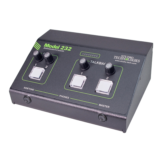
Model 232 Announcer's Console
User Guide
Issue 5, October 2021
This User Guide is applicable for serial numbers
M232-00151 and later with main firmware version 3.02 and later
and STcontroller software application version 3.05.00 and later.
Copyright © 2021 by Studio Technologies, Inc., all rights reserved
studio-tech.com
50684-1021 Issue 5
Advertisement
Table of Contents

Related Manuals for Studio Technologies 232


Summary of Contents for Studio Technologies 232
- Page 1 This User Guide is applicable for serial numbers M232-00151 and later with main firmware version 3.02 and later and STcontroller software application version 3.05.00 and later. Copyright © 2021 by Studio Technologies, Inc., all rights reserved studio-tech.com 50684-1021 Issue 5...
- Page 2 This page intentionally left blank.
-
Page 3: Table Of Contents
Table of Contents Revision History ................4 Introduction ..................5 Getting Started ................8 Dante Configuration ............... 12 Model 232 Configuration ..............14 Operation ..................23 Technical Notes ................31 Specifications ................. 39 Appendix A: STcontroller Default Configuration Values ....41 Appendix B: 3-Pin Header Connector Details ........ -
Page 4: Revision History
Adds technical note regarding level attenuation in Dante Aux and Talkback transmitter (output) channels when Analog Mic Output is configured for Switched. Issue 1, August 2020: • Initial release. Issue 5, October 2021 Model 232 User Guide Page 4 Studio Technologies, Inc. -
Page 5: Introduction
I/O interface or audio console can be supported. The Model 232 was designed to meet two main goals: supporting great audio quality and pro- With six Dante audio inputs and an integrated viding an extensive set of configurable features. - Page 6 ANNOUNCER’S CONSOLE The amount of flexibility provided in the Model connected using a 4-pin XLR connector. A 232 allows it to meet the needs of virtually all broadcast headset or handheld (“stick”) micro- on-air announcer applications. And using the phone can be directly connected to the unit’s Studio Technologies’...
- Page 7 Extensive configuration choices allow by way of seven Dante receiver (input) chan- the operation of the pushbutton switches and nels and pass into the Model 232’s 32-bit logic associated output channels to be optimized to circuitry. Four channels are associated with meet the needs of specific applications.
-
Page 8: Getting Started
(GigE) twisted-pair Ethernet interfaces. These nal source of 12 volts DC to power the Model 1000BASE-T interconnections are made by 232. If this is the case then a power supply way of Neutrik® etherCON RJ45 connectors. would need to be obtained separately. - Page 9 Refer to the Technical Notes An external source of 12 volts DC can be section of this guide for details. connected to the Model 232 by way of a 4- pin male XLR connector which is located on One or Two Ethernet Connections the unit’s back panel.
- Page 10 PoE supply. If the PoE source becomes This input could be connected to the Model inoperative the 12 volts DC source will pro- 232 by way of the analog microphone output vide the Model 232’s power. No interruption connector. This would not create a problem...
- Page 11 2-conductor No preamplifier or other active circuitry im- (“tip and sleeve”) plug. When such a plug is pacts the path from the Model 232’s analog inserted into the Model 232’s headphone out- microphone input connector to the Model put jack the right headphone output channel 232’s analog microphone output connector.
-
Page 12: Dante Configuration
(output) sources can be routed For audio to correctly pass to and from the to the seven Dante receiver (input) channels Model 232 requires, at a minimum, that sev- associated with the Model 232. The exact eral Dante-related parameters be configured. - Page 13 Redundancy dant then separate IP addresses and related network parameters will be assigned to the The Model 232 allows connection of two Eth- Primary-PoE and Secondary Ethernet ports. ernet signals. Two RJ45 jacks are located on the unit’s back panel and are labeled Primary- By default, the Model 232’s Dante IP address...
-
Page 14: Model 232 Configuration
P48 source is displayed both in STcontroller and by way of an orange LED that is located Changes made using STcontroller will be on the Model 232’s back panel adjacent to the immediately reflected in the unit’s operation; analog microphone input connector. Select no Model 232 reboot is required. - Page 15 An audio signal that arrives by ic “slider.” It also includes an indication of way of the Model 232’s Dante Mic In receiver when the limiter function is actively controlling (input) channel can also be utilized. Any audio the signal level.
- Page 16 “chain.” audio signal associated with a specific rotary If necessary, adjust the gain of the Model 232’s encoder and related input function. RGB analog microphone preamplifier to achieve the (red-green-blue) LEDs are located within desired result.
- Page 17 The Hot Mic function can be very useful but has the On the Model 232’s back panel is a 3-pin potential for abuse. By the very nature of a male XLR connector that is labeled Mic Out.
- Page 18 If “mix-minus” audio is being supplied to stall one or two connectors in the Model 232’s the Model 232 then selecting a mode which back panel. Refer to the Technical Notes sec- enables sidetone can be an important means tion of this guide for details.
- Page 19 Remote Control In 1 with the addition of a red when it’s inactive. Upon Model 232 power choice of Main Out Tally. When this con- up the main button will be in its inactive state figuration choice is selected then the physi- and its red LED will be lit.
- Page 20 LED will be lit whenever the function is active. to the Dante Talkback receiver (input) channel Upon Model 232 power up the function will be will be routed to the analog and Dante head- in its inactive state and its LED will not be lit.
- Page 21 Upon Model sent out an active Model 232 talkback chan- 232 power up the talkback button will be in its nel that is configured for either the Talk or the inactive state and its LED will not be lit.
- Page 22 This might be appropriate if a present on this Dante Talkback receiver (in- Model 232 is being used as an intercom station put) channel can be routed to either or both or in a stage manager console application.
-
Page 23: Operation
Primary-PoE Ethernet connector on the of Dante “subscriptions,” to the receiver and Model 232’s back panel. It will light green if an transmitter channels on associated Dante- Ethernet signal that is providing PoE power enabled equipment. - Page 24 232 is not synchronized with a Dante network. microphone preamplifier should be reduced. It will light solid green when the Model 232 is Refer to the Microphone Input – Analog Gain synchronized with a Dante network and an...
- Page 25 Model 232 audio low a specific Model 232 unit to be identified. performance from being achieved. Both applications include an “eyeball” icon that when clicked will activate the Model 232’s...
- Page 26 “cough” function that’s frequently Although a user probably won’t be aware of utilized in on-air broadcast applications. The it, the Model 232 provides a Dante transmit- main button will light green when the main ter (output) channel designated as Aux. How function is active and red when it is not active.
- Page 27 LED will flash contin- plications a Model 232 can support. While the uously. No voice or tone audio will be present product’s title includes the text “Announcer’s on the associated Dante transmitter (output) Console,”...
- Page 28 MODEL 232 ANNOUNCER’S CONSOLE the left side of the Model 232’s front panel, selected microphone input source. Exactly is used to adjust the sidetone level. Another when the sidetone function will operate will rotary potentiometer, located on the right side depend on a STcontroller configuration set- of the Model 232’s front panel and labeled...
- Page 29 Four rotary encoders are provided on the front (“tapped”). panel of the Model 232. Two of the rotary For user assistance, the eight LEDs associ- encoders are located above the Main push- ated with the multi-purpose display on the button switch.
- Page 30 In most cases the talkback inputs to have their signal present Model 232 will be used on-air and the default display function active. mode, Mutes, will be appropriate. When this...
-
Page 31: Technical Notes
This is provided so that the Model 232 can talkback pushbutton switches. be utilized in intercom environments where call One remote control input can also be config- light signals are present. - Page 32 (static) configuration using the Dante Level Controller software application. In the unfor- tunate event that a specific Model 232’s IP A level anomaly can occur with the Model address is “lost” there are several techniques 232’s Dante Aux and Talkback transmitter that may prove useful.
- Page 33 In this case the output level on a Dante Talkback transmitter (output) channel would Two spare connector locations, labeled A always be 1 to 3 dB less than the Model 232’s and B, are provided on the Model 232’s back Dante reference level. This wouldn’t typically panel.
- Page 34 Please refer to the website for details on what that prints white text on a black background is available. would be effective for use with the Model 232. The spare connector locations are compatible The Brother label cassette number TX-3151, with the Neutrik DL-series of connectors.
- Page 35 The actual action that creates an IFB “feed” connector terminals or “solder cups” can be within the Model 232 is very simple. If a tone insulated from each other. It will also provide is detected on the audio signal arriving on some strain relief to the solder joints.
- Page 36 Model 232. place: the program audio source being routed That’s an artistic choice that the Model 232 is to the left headphone channel will attenuate not intended to be involved with.
- Page 37 Model review the list of identified devices and select 232, the name of the zip file itself will include the specific Model 232 from which you want the file’s version number. For example, a file to determine its application firmware versions.
- Page 38 From within STcontroller select the specific Model 232 unit 6. At this time the Model 232 will be function- ing with the newly loaded firmware and the for which you want to restore its defaults. Select USB flash drive can be removed.
-
Page 39: Specifications
(will pass phantom power in either direction) Control Input 2 (only one function can be configured at a Muting: solid-state relay contacts, 60 dB attenuation time) @ 1 kHz Model 232 User Guide Issue 5, October 2021 Studio Technologies, Inc. Page 39... - Page 40 Analog Microphone Input: 3-pin header located on the analog circuit board Spare Connector Locations: 2 Allows a Studio Technologies’ cable assembly or option module to be installed. Also compatible with Neutrik NC*D-L-1 connectors (*=3F, 3M, 5M, 6F, 6FS, etc.). Configuration: requires Studio Technologies’...
-
Page 41: Appendix A: Stcontroller Default Configuration Values
Talkback – Listen Mode: Always Talkback – Button Mode: Hybrid Talkback – Button Function: Talk Talkback – Impact on Main Output: Mutes Talkback – Tone Detect Function: None Model 232 User Guide Issue 5, October 2021 Studio Technologies, Inc. Page 41... -
Page 42: Appendix B: 3-Pin Header Connector Details
ANNOUNCER’S CONSOLE Appendix B: 3-Pin Header Connector Details The following list provides details on the 3-pin header connectors located on the Model 232’s printed circuit boards. Shown are both reference numbers and associated functions. I. Header on the Analog Board:... -
Page 43: Appendix C: Block Diagram
MODEL 232 ANNOUNCER’S CONSOLE Appendix C: Block Diagram The following block diagram shows a simplified version of the microphone input and microphone output circuitry. Model 232 User Guide Issue 5, October 2021 Studio Technologies, Inc. Page 43...
Need help?
Do you have a question about the 232 and is the answer not in the manual?
Questions and answers